
 Shenheng Elektrik Ekipmanları Ticaret Limited Şirketi.



transient recovery voltage circuit breaker requires a clear engineering boundary before it can support a purchase, inspection or commissioning decision. Transient recovery voltage, or TRV, is the voltage that appears across a circuit breaker’s terminals after current interruption. The breaker must regain dielectric strength faster than the recovery voltage rises. TRV depends on the network, source, transformer, cable, fault location, earthing and interruption instant, so a breaker selection cannot rely on normal voltage and short-circuit RMS current alone.
Define TRV and recovery duty
TRV is a time-varying recovery voltage after the arc is extinguished. Peak value, rate of rise and the relevant fault type all matter. The breaker’s dielectric recovery and tested duty must be compatible with the system transient.
Keep the voltage class, fault current, network topology, power factor or time constant, fault location, source contribution and clearing sequence visible in the study. Do not compare a TRV peak with a breaker RMS current rating.
Review the network source and fault path
Transformer leakage, cable capacitance, busbar geometry, line length, grounding and source strength shape the transient. Short-line, terminal, transformer and bus faults can produce different stresses.
Ask the system engineer for the worst credible fault at each breaker terminal. Re-check after a transformer, cable, capacitor, generator or earthing change. A value from a neighboring feeder is not evidence for this breaker.
Match the breaker and assembly evidence
The interrupter, contact gap, insulation, grading, truck, primary disconnects, shutters and enclosure form the tested arrangement. A standalone breaker test does not validate a modified cubicle.
Request the relevant design verification or type-test scope and compare rated voltage, short-circuit duty, operating sequence and TRV envelope. Keep the approved drawings and routine tests with the asset file.
Coordinate protection and interruption time
Relay detection, CT performance, breaker opening time and arc duration affect the transient and the thermal or mechanical duty. A protection change can alter the interruption point and the stress seen by the breaker.
Record settings, CT data, breaker operating time and backup clearing. Confirm the breaker can perform the required sequence without relying on an unverified emergency delay or a forced interlock bypass.
Consider mitigation carefully
Surge arresters, pre-insertion devices, controlled switching or network changes can influence transients, but each option has its own design and maintenance limits. Do not add a device simply because a waveform looks alarming.
Compare the mitigation with the system study, insulation coordination, space, control logic and verified assembly. Obtain an approved design change and test plan before installation.
Verify with tests and records
Commissioning should confirm breaker timing, mechanism, interlocks, position feedback, protection logic and the intended test boundary. A field waveform is useful only when instrument bandwidth, wiring and test method are documented.
Retain raw records, instrument details, settings, fault-study revision, deviations and final as-built drawings. Revisit TRV when the network or breaker arrangement changes.
Separate interruption current from recovery-voltage duty
A circuit breaker’s short-circuit current rating and its recovery-voltage duty describe different stresses. After current interruption, the voltage appearing across the opening contacts depends on the connected network and the interrupted fault. The breaker must recover its insulating capability while that voltage develops. A satisfactory current rating therefore does not automatically establish suitability for every transient recovery voltage condition. Begin the review with the actual circuit arrangement and the manufacturer’s assessed duties rather than treating the maximum fault-current figure as the only acceptance criterion.
Define the fault locations and operating configurations that the study must cover. A transformer-limited fault, a fault near the breaker and other network conditions can present different recovery-voltage characteristics. Record which sources, cables, transformers, reactors and grounding arrangements are in service for each case. Avoid assuming that the configuration producing the highest fault current also produces the most demanding recovery-voltage waveform. The engineer’s study should explain which cases govern and how they compare with the applicable breaker capability and test evidence.
Review the waveform characteristics specified by the applicable standard and equipment evidence, including the voltage development over time. Do not invent a universal acceptable rate of rise or apply a numerical limit from a different voltage class. Obtain the relevant manufacturer’s data and the project study assumptions. If a simulation is used, retain the model boundaries, input data and sensitivity review so the result can be reproduced. Cable length, transformer parameters or added equipment may change the modeled response; a later network modification can therefore require another review even if the installed breaker has not changed.
Mitigation should address the identified cause and be checked against the complete system. Adding a surge arrester or capacitor without an engineering assessment can introduce different stresses or fail to address the governing duty. If the study indicates that the specified breaker capability is inadequate, obtain a manufacturer-supported solution and revise the design documentation before acceptance. Keep the protection settings, interruption timing assumptions, network study and breaker evidence together. This review is a specification and coordination task; it does not authorize field personnel to create faults or conduct unapproved switching experiments to test the conclusion.
Standartları ve üretici kanıtlarını birlikte kullanın
Standartlar çerçeveyi, test kavramlarını ve terminolojiyi tanımlarken, üretici belgeleri ise tedarik edilen ekipmanın doğrulanmış yapısal ve işletme sınırlarını belirler. Bir standart bağlantı, doğrulanmamış bir değişikliğin kabul edilebilirliğini kanıtlayamazken, bir broşür de proje spesifikasyonunu veya güvenlik kurallarını değiştiremez.
Alım için standart sürüm, tasarım doğrulama veya tip test kapsamı, rutin test kayıtları, montaj sınırları ve herhangi bir yükseklik veya ortam düzeltmesi isteyin. Kanıtları varlık kaydına ekleyin. Bir sonuç tartışılırsa, sayıları karşılaştırmadan önce tanımları, test koşullarını ve sınırları karşılaştırın.
Kurulum ve devreye alma planı
Kurulum kalitesi, ses tasarımının saha performansında kalıp kalıp olup olmamasına karar veren önemli bir faktördür. Güçlendirme öncesinde temellerin, erişim yollarının, kaldırma işlemlerinin, boşlukların, havalandırmanın, kablo büküm yarıçapının, topraklama işleminin, etiketlerin ve kontrol arayüzlerinin uygunluğunu doğrulayın. Onaylı yöntem bildirimi ve izin sistemini kullanın. Sade bir kabin, her bağlantının, kilitlemenin veya sensörün doğru şekilde bağlandığının kanıtı değildir.
Kurulum, doküman kontrollerinden görsel incelemeye, mekanik çalışmaya, elektrik bağlantılarına, fonksiyonel mantığa, koruma veya kontrol testlerine ve son olarak restore edilmeye geçmelidir. Test veya inceleme sırasında bir tehlike ortaya çıkarsa, cihazın kimliğini, ayarları, ham değerleri, istisnaları ve incelemeyi yapan kişiyi kaydetmek. Test veya inceleme sırasında cihazın izole edilmesini sağlamak.
Kontrol değişiklikleri ve devir
Kablo hattı yönlendirmesi, röle ayarı, musluk konumu, soğutma yolu veya topraklama bağlantısı gibi değişiklikler orijinal tasarım esasını değiştirebilir. Kontrollü bir değişim süreci için bir sahibi, teknik inceleme, çizim revizyonu ve kabul belgesi kullanın. Geçiş öncesi geçici test düzenlemeleri kaldırılarak ya da açıkça işaretlenmelidir.
Son pakette as-built çizimler, test formları, onaylı ayarlar, ekipman tanımları, bakım talimatları, sapmalar ve eğitim kayıtları yer almalıdır. Bir gelecekteki operatör, kararı hafızaya veya etiketlenmemiş bir fotoğrafa bel bağlamadan yeniden oluşturabilmelidir.
Güvenlik bilgisi
Elektrikli ekipmanlar enerji depolayabilir ve birden fazla kaynaktan beslenebilir. Bu makale bir anahtarlama talimatı değildir. Yetkili personel yerel yönetmelikleri, izolasyon, voltaj yoklama, topraklama ve denetim gerekliliklerini takip etmelidir. Enerjili bir bölüme ulaşmak veya kilidi bozmak suretiyle ölçüm yapmamak.
Bir test başarısız olursa, muhafaza hasar görür, anormal ses veya akım görülür veya gerçek konfigürasyon belirsizse varlığı güvenli bir durumda tutun ve sorumlu mühendisle iletişime geçin. Teşhis yapılmadan tekrarlanan çalıştırma hasarı ve riskleri artırabilir.
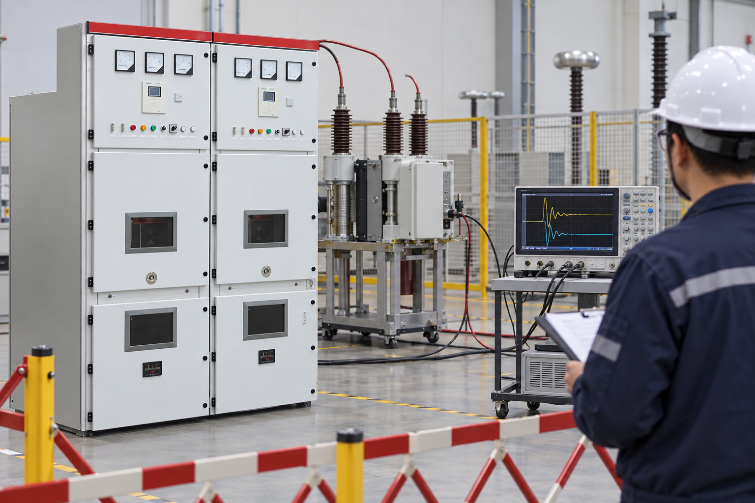
Bir projede sonucu nasıl kullanabiliriz?
Serbest bırakılan tasarım ve nihai ekipman kimliği ile başlayın. Çalışma durumu, ölçüm noktası, çevre koşulları ve kanıtın desteklemesi gereken karar hususlarını not alın. Ardından kaydı geçerli standart, üretici talimatı ve proje kabul planıyla karşılaştırın. Bir ön koşul eksikse, boşluğu genel bir değerle doldurmak yerine ögeyi açık tutun. Bu, tedarik, devreye alma ve işletme ekiplerine aynı referans noktası sunar.
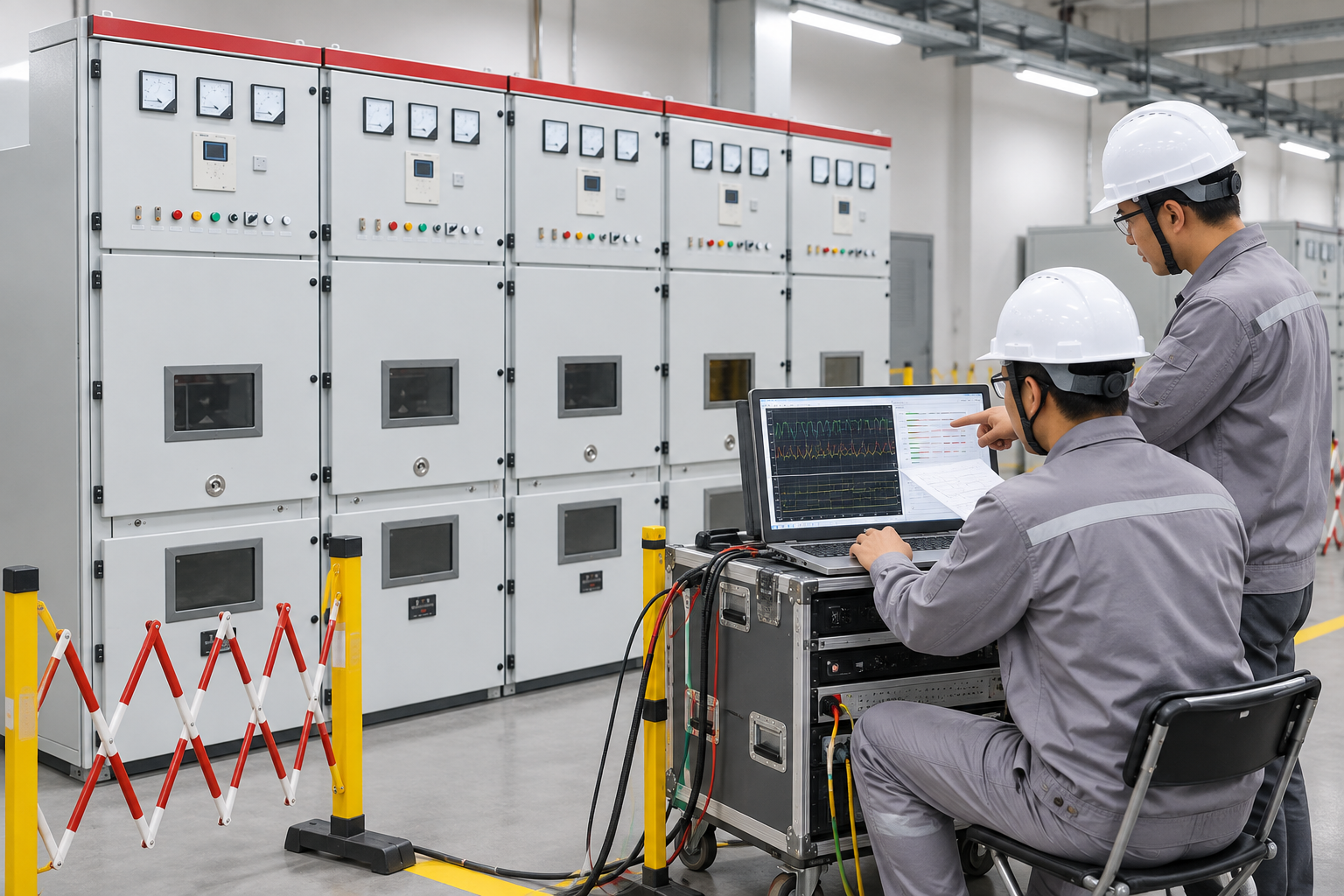
Bir tedarikçiyle ilgili bir soruşturma için, hesaplama esaslarını, doğrulanan düzenlemeleri, limitleri, test kayıtlarını ve sapmaları öğrenin. Şantiye çalışmaları için ise kişi, cihaz, tarih, izolasyon sınırları ve restorasyon kontrolünü not alın. Bir sonraki adımı onaylamak için gerekli olan tek bilgiyi gizleyen uzun bir rapordan daha kısa bir not daha yararlıdır.
| Kontrol edin | Kanıtlar | Karar kullanım |
|---|---|---|
| Tanım | Sınır, ekipman kimliği ve çalışma durumu | Farklı ekiplerin farklı miktarları karşılaştırmasını engeller. |
| Design temeli | Değerlendirmeler, çevre ve görev varsayımları | Cevabı gerçek kurulumla ilişkilendirir. |
| Onaylama | Onaylı yöntem, araç, ham sonuç ve kabul kriterleri | Denetlenebilir bir kayıt oluşturur. |
| Denetim kontrolü | Değişiklik, gözden geçirme sahibi ve as-built revizyon | Gizli alan değişikliklerinin risk oluşturmasına engel olur. |
| Devir teslim | Ayarlar, testler, fotoğraflar, bakım ve istisnalar | Güvenli gelecekteki çalışmayı destekler. |
İlgili ürün ve mühendislik kılavuzları
Shenheng ürün bağlamı için bkz. ilgili ürün sayfası. Genel konuya ilişkin daha detaylı bilgi için okuyun Ana mühendis kılavuzu. İlgili okuma: ilk ilgili rehber ve İkinci ilgili rehber.
Kaynaklar ve standartlar
IEC 62271-100: Alternating-current circuit-breakers · IEC 62271-200: AC metal-enclosed switchgear
Sistem bağlamı için video
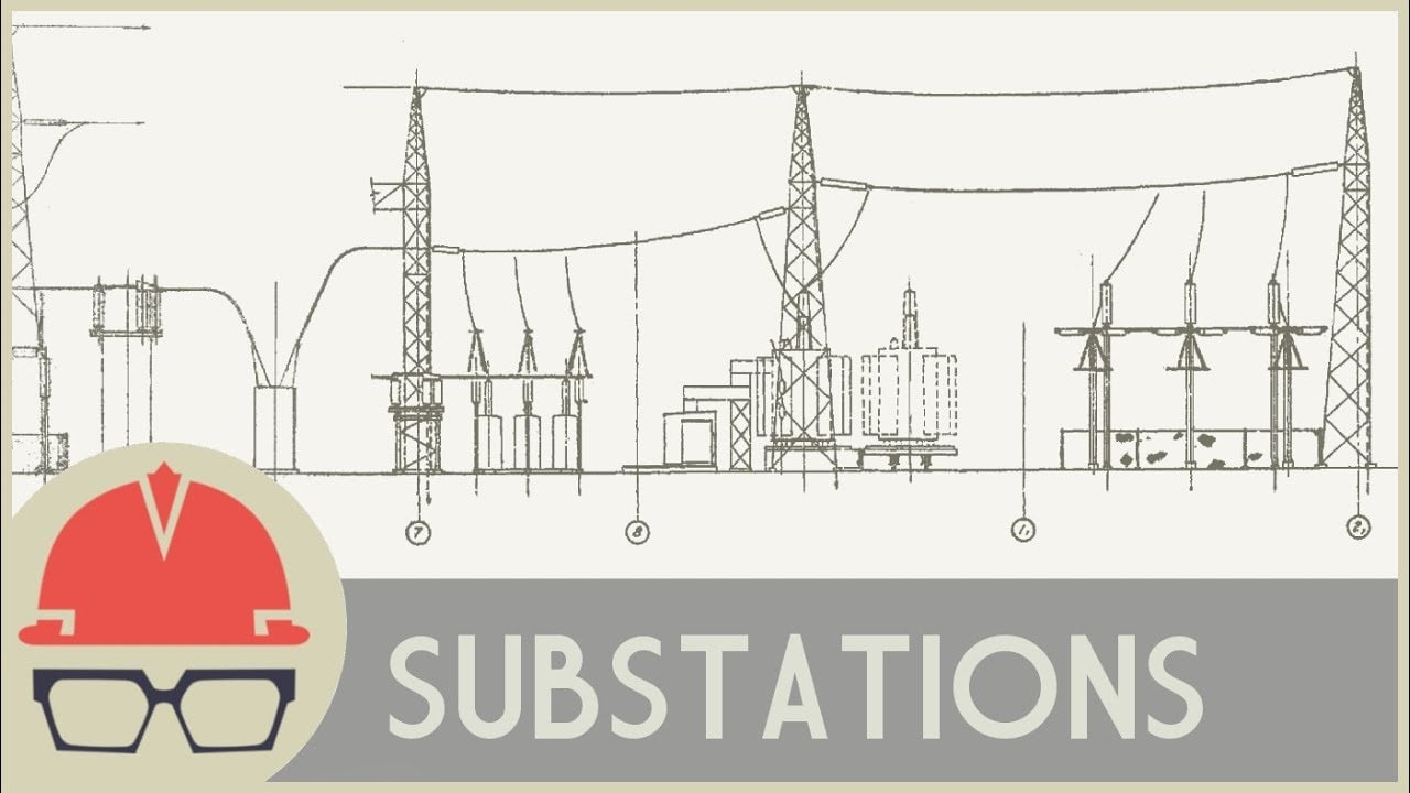
Bu tarafsız Practical Engineering anlatımı, trafo merkezleri, transformatörler ve devre elemanları hakkında bilgi sunuyor. Bu anlatım, devre kesme veya test talimatı değil, eğitimsel bir bağlam sunuyor.
Sık sorulan sorular
İlk adım nedir?
Define the exact transient recovery voltage circuit breaker boundary, equipment identity and operating state before comparing a value or feature.
Bir katalog sayfası proje mühendisliğini değiştirebilir mi?
Hayır. Bağlantılı ürün sayfası ilgili Shenheng ekipman ailesini belirtir. Teslim edilen model, aksesuarlar, standartlar ve proje kabul planı nihai kararı belirler.
Ne tür kanıtlar saklanmalı?
Onaylanmış çizimi, hesaplamayı veya test yöntemini, ham ölçümleri, fotoğrafları, cihaz detaylarını, sapmaları, ayarları ve son haliyle inşa edilen ölçüleri saklayın.
Bu yazı canlı çalışmayı onaylıyor mu?
Hayır. Yetkili personel, site elektrik güvenliği programını, izolasyon ve üretici talimatlarını takip etmelidir.




