
 申恒電力設備有限公司.



transient recovery voltage circuit breaker requires a clear engineering boundary before it can support a purchase, inspection or commissioning decision. Transient recovery voltage, or TRV, is the voltage that appears across a circuit breaker’s terminals after current interruption. The breaker must regain dielectric strength faster than the recovery voltage rises. TRV depends on the network, source, transformer, cable, fault location, earthing and interruption instant, so a breaker selection cannot rely on normal voltage and short-circuit RMS current alone.
Define TRV and recovery duty
TRV is a time-varying recovery voltage after the arc is extinguished. Peak value, rate of rise and the relevant fault type all matter. The breaker’s dielectric recovery and tested duty must be compatible with the system transient.
Keep the voltage class, fault current, network topology, power factor or time constant, fault location, source contribution and clearing sequence visible in the study. Do not compare a TRV peak with a breaker RMS current rating.
Review the network source and fault path
Transformer leakage, cable capacitance, busbar geometry, line length, grounding and source strength shape the transient. Short-line, terminal, transformer and bus faults can produce different stresses.
Ask the system engineer for the worst credible fault at each breaker terminal. Re-check after a transformer, cable, capacitor, generator or earthing change. A value from a neighboring feeder is not evidence for this breaker.
Match the breaker and assembly evidence
The interrupter, contact gap, insulation, grading, truck, primary disconnects, shutters and enclosure form the tested arrangement. A standalone breaker test does not validate a modified cubicle.
Request the relevant design verification or type-test scope and compare rated voltage, short-circuit duty, operating sequence and TRV envelope. Keep the approved drawings and routine tests with the asset file.
Coordinate protection and interruption time
Relay detection, CT performance, breaker opening time and arc duration affect the transient and the thermal or mechanical duty. A protection change can alter the interruption point and the stress seen by the breaker.
Record settings, CT data, breaker operating time and backup clearing. Confirm the breaker can perform the required sequence without relying on an unverified emergency delay or a forced interlock bypass.
Consider mitigation carefully
Surge arresters, pre-insertion devices, controlled switching or network changes can influence transients, but each option has its own design and maintenance limits. Do not add a device simply because a waveform looks alarming.
Compare the mitigation with the system study, insulation coordination, space, control logic and verified assembly. Obtain an approved design change and test plan before installation.
Verify with tests and records
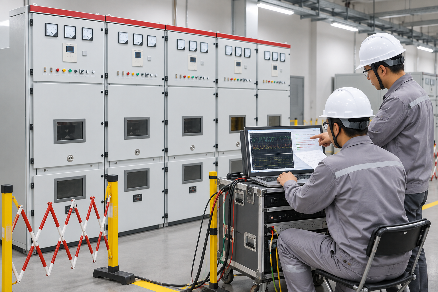
Commissioning should confirm breaker timing, mechanism, interlocks, position feedback, protection logic and the intended test boundary. A field waveform is useful only when instrument bandwidth, wiring and test method are documented.
Retain raw records, instrument details, settings, fault-study revision, deviations and final as-built drawings. Revisit TRV when the network or breaker arrangement changes.
Separate interruption current from recovery-voltage duty
A circuit breaker’s short-circuit current rating and its recovery-voltage duty describe different stresses. After current interruption, the voltage appearing across the opening contacts depends on the connected network and the interrupted fault. The breaker must recover its insulating capability while that voltage develops. A satisfactory current rating therefore does not automatically establish suitability for every transient recovery voltage condition. Begin the review with the actual circuit arrangement and the manufacturer’s assessed duties rather than treating the maximum fault-current figure as the only acceptance criterion.
Define the fault locations and operating configurations that the study must cover. A transformer-limited fault, a fault near the breaker and other network conditions can present different recovery-voltage characteristics. Record which sources, cables, transformers, reactors and grounding arrangements are in service for each case. Avoid assuming that the configuration producing the highest fault current also produces the most demanding recovery-voltage waveform. The engineer’s study should explain which cases govern and how they compare with the applicable breaker capability and test evidence.
Review the waveform characteristics specified by the applicable standard and equipment evidence, including the voltage development over time. Do not invent a universal acceptable rate of rise or apply a numerical limit from a different voltage class. Obtain the relevant manufacturer’s data and the project study assumptions. If a simulation is used, retain the model boundaries, input data and sensitivity review so the result can be reproduced. Cable length, transformer parameters or added equipment may change the modeled response; a later network modification can therefore require another review even if the installed breaker has not changed.
Mitigation should address the identified cause and be checked against the complete system. Adding a surge arrester or capacitor without an engineering assessment can introduce different stresses or fail to address the governing duty. If the study indicates that the specified breaker capability is inadequate, obtain a manufacturer-supported solution and revise the design documentation before acceptance. Keep the protection settings, interruption timing assumptions, network study and breaker evidence together. This review is a specification and coordination task; it does not authorize field personnel to create faults or conduct unapproved switching experiments to test the conclusion.
標準規格とメーカーの証拠を併用する
標準規格はフレームワーク、テストコンセプト、用語を定義しますが、メーカーのドキュメントは供給された機器の検証された構造および動作限界を規定します。標準化されたリンクは、未検証の変更が許容されることを証明するものではなく、パンフレットはプロジェクト仕様または安全規則に代わるものではありません。.
調達については、標準版、設計検証またはタイプテストの範囲、日常検査記録、設置制限、および高度や環境の補正を依頼してください。証拠は資産記録に保管してください。結果が異議を唱えられた場合は、数値の比較前に定義、試験条件、および境界条件を比較してください。.
設置および試運転計画
設置の品質は、現場で音響設計がそのまま残るかどうかを左右します。電源投入前に、基礎、アクセス、持ち上げ、クリアランス、換気、ケーブルの曲げ半径、アース接続、ラベル、および制御インターフェースを確認してください。承認済みの方法書および許可システムを使用してください。きちんとしたキャビネットは、すべての接続、インターロック、またはセンサーが正しく接続されていることを示すものではありません。.
稼働開始は文書確認から視覚検査、機械動作、電気的連続性、機能的論理、保護または制御試験、最終的な修復へと移行すべきです。機器の識別、設定、原値、例外、および検査を行った担当者の記録を記録してください。テストまたは検査により危険性が生じる場合は、機器を隔離してください。.
制御の変更と引き継ぎ
ケーブルルート、リレー設定、タップ位置、冷却経路、またはアース接続の変更は、元の設計基準を変化させる可能性があります。管理者の同意を得た上で、制御された変更プロセスを実施し、技術審査、図面の修正、および承認証拠を保持してください。一時的なテスト手順は引き渡し前に除去または明確に記号化する必要があります。.
最終的なパッケージには、現況図面、テストシート、承認済みの設定、機器識別情報、メンテナンス手順、逸脱点、およびトレーニング記録が含まれるべきです。将来のオペレータは、メモリーや無記名写真に頼ることなく、その決定を再現できるようになるべきです。.
安全上の注意
電気機器はエネルギーを保持し、複数の供給源から電力を供給を受けることができます。この記事はスイッチングに関する指示ではありません。資格を有する職員は、地域の規制、絶縁、電圧の有無の確認、接地、監督の要件に従わなければなりません。電力を供給されているコンパートメントに手を伸ばしたり、ロックを解除したりして測定を行ってはなりません。.
テストが失敗した場合、筐体が損傷している、異常なノイズや放電が発生している、実際の構成が不明な場合は、資産を安全な状態に維持し、担当エンジニアに報告してください。診断なしでの繰り返し電源投入は損傷やリスクを増大させる可能性があります。.

プロジェクトでその結果をどのように利用するか
まず、リリースされた設計と最終的な機器の仕様から始めましょう。操作状態、測定ポイント、環境条件、およびその決定の根拠を記載してください。その後、記録を該当する標準、製造元の指示、およびプロジェクトの承認計画と比較します。前提条件が欠けている場合は、一般的な値でそのギャップを埋めるのではなく、その項目をそのまま残しておいてください。これにより、調達、導入、運用チームに同じ基準が与えられます。.
仕入先からの問い合わせでは、計算方法、確認された手順、制限事項、試験記録、および逸脱点について確認してください。現場作業では、担当者、機器、日付、隔離境界、および復旧確認を記録してください。次のステップの承認に必要な事実を隠してしまう長い報告書よりも、簡潔な記録の方が有用です。.
| 確認 | 証拠 | 決定の使用 |
|---|---|---|
| 定義 | 境界、機器の識別、および動作状態 | 異なるチームが異なる数量を比較することを防ぎます。. |
| 設計基準 | 評価、環境、および義務の前提条件 | 解答と実際のインストールをリンクします。. |
| 確認 | 承認された方法、器具、生の結果、および承認基準 | 監査可能な記録を作成します。. |
| 変更管理 | 偏差値、レビューオーナー、および構築時点での修正内容の確認 | 隠れたフィールドの変更がリスクとなるのを防ぐ。. |
| 引き継ぎ | 設定、テスト、写真、メンテナンス、および例外 | 安全な将来の運用をサポートします。. |
関連製品およびエンジニアリングガイド
Shenheng製品の組み合わせに関する詳細は、こちらをご覧ください。 該当する製品ページ. より広範なトピックについては、こちらをお読みください。 親エンジニアリングガイド. 関連する記事: 最初の関連ガイド そして 2つ目の関連ガイド.
情報源と基準
IEC 62271-100: Alternating-current circuit-breakers · IEC 62271-200: AC metal-enclosed switchgear
システムコンテキスト用の動画
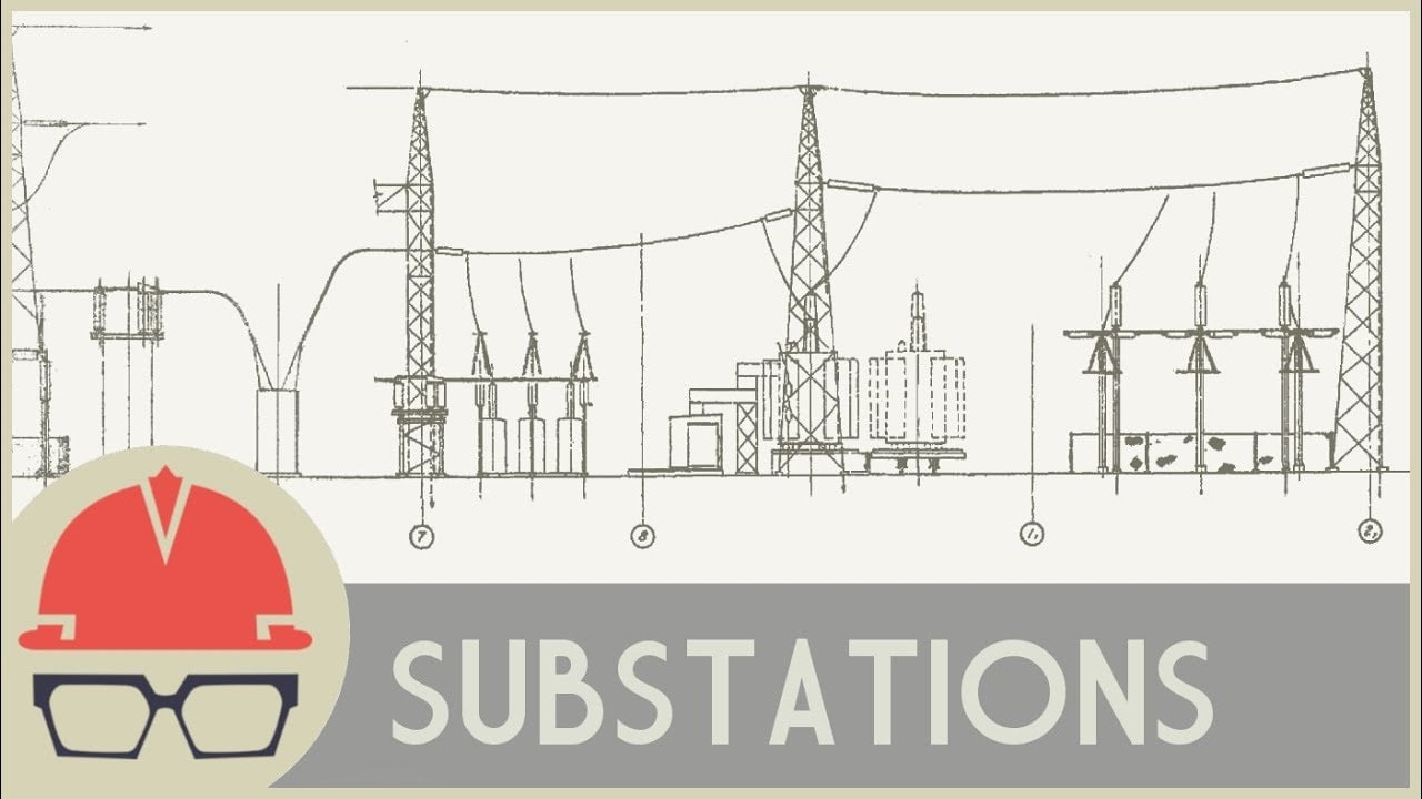
このニュートラルなPractical Engineeringの解説では、変電所、変圧器、スイッチ装置の基礎知識が紹介されています。これはスイッチングやテストに関する指示ではなく、教育的な内容です。.
よくある質問
最初のステップは何ですか?
Define the exact transient recovery voltage circuit breaker boundary, equipment identity and operating state before comparing a value or feature.
カタログページがプロジェクトエンジニアリングを置き換えることは可能か?
いいえ。リンクされた製品ページには、関連するShenheng機器ファミリーが記載されています。付属のモデル、アクセサリー、規格、およびプロジェクトの承認計画が最終的な決定を下します。.
どのような証拠を保持すべきですか?
承認された図面、計算方法または試験方法、原データ、写真、機器の詳細、偏差、設定、および最終的な竣工図面を保管してください。.
この記事はライブワークを許可していますか?
いいえ。資格を有する職員は、現場の電気安全プログラム、絶縁手順、および製造元の指示に従う必要があります。.




