บริษัท เสินเฮิง พาวเวอร์ อีควิปเมนท์ จำกัด.



transient recovery voltage circuit breaker requires a clear engineering boundary before it can support a purchase, inspection or commissioning decision. Transient recovery voltage, or TRV, is the voltage that appears across a circuit breaker’s terminals after current interruption. The breaker must regain dielectric strength faster than the recovery voltage rises. TRV depends on the network, source, transformer, cable, fault location, earthing and interruption instant, so a breaker selection cannot rely on normal voltage and short-circuit RMS current alone.
Define TRV and recovery duty
TRV is a time-varying recovery voltage after the arc is extinguished. Peak value, rate of rise and the relevant fault type all matter. The breaker’s dielectric recovery and tested duty must be compatible with the system transient.
Keep the voltage class, fault current, network topology, power factor or time constant, fault location, source contribution and clearing sequence visible in the study. Do not compare a TRV peak with a breaker RMS current rating.
Review the network source and fault path
Transformer leakage, cable capacitance, busbar geometry, line length, grounding and source strength shape the transient. Short-line, terminal, transformer and bus faults can produce different stresses.
Ask the system engineer for the worst credible fault at each breaker terminal. Re-check after a transformer, cable, capacitor, generator or earthing change. A value from a neighboring feeder is not evidence for this breaker.
Match the breaker and assembly evidence
The interrupter, contact gap, insulation, grading, truck, primary disconnects, shutters and enclosure form the tested arrangement. A standalone breaker test does not validate a modified cubicle.
Request the relevant design verification or type-test scope and compare rated voltage, short-circuit duty, operating sequence and TRV envelope. Keep the approved drawings and routine tests with the asset file.
Coordinate protection and interruption time
Relay detection, CT performance, breaker opening time and arc duration affect the transient and the thermal or mechanical duty. A protection change can alter the interruption point and the stress seen by the breaker.
Record settings, CT data, breaker operating time and backup clearing. Confirm the breaker can perform the required sequence without relying on an unverified emergency delay or a forced interlock bypass.
Consider mitigation carefully
Surge arresters, pre-insertion devices, controlled switching or network changes can influence transients, but each option has its own design and maintenance limits. Do not add a device simply because a waveform looks alarming.
Compare the mitigation with the system study, insulation coordination, space, control logic and verified assembly. Obtain an approved design change and test plan before installation.
Verify with tests and records
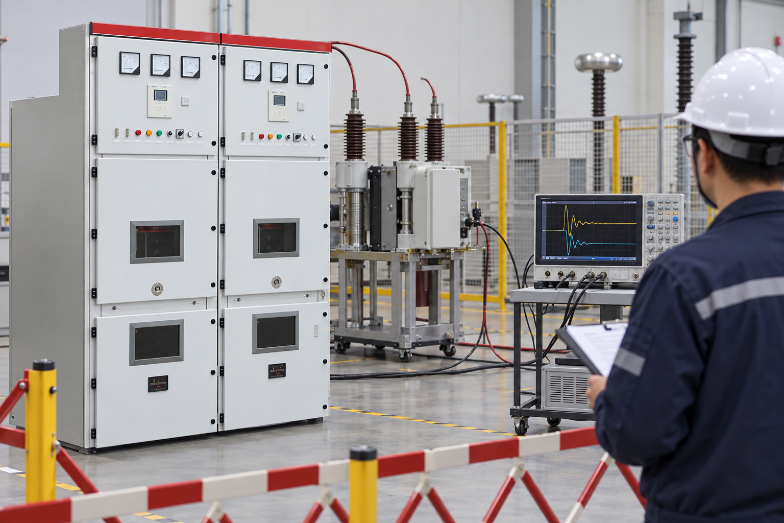
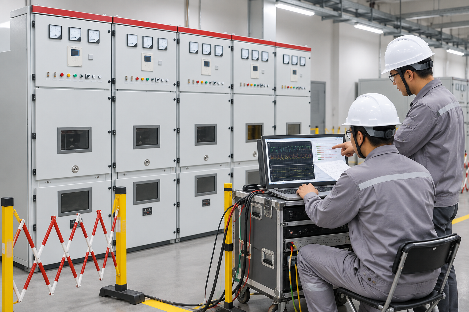
Commissioning should confirm breaker timing, mechanism, interlocks, position feedback, protection logic and the intended test boundary. A field waveform is useful only when instrument bandwidth, wiring and test method are documented.
Retain raw records, instrument details, settings, fault-study revision, deviations and final as-built drawings. Revisit TRV when the network or breaker arrangement changes.
Separate interruption current from recovery-voltage duty
A circuit breaker’s short-circuit current rating and its recovery-voltage duty describe different stresses. After current interruption, the voltage appearing across the opening contacts depends on the connected network and the interrupted fault. The breaker must recover its insulating capability while that voltage develops. A satisfactory current rating therefore does not automatically establish suitability for every transient recovery voltage condition. Begin the review with the actual circuit arrangement and the manufacturer’s assessed duties rather than treating the maximum fault-current figure as the only acceptance criterion.
Define the fault locations and operating configurations that the study must cover. A transformer-limited fault, a fault near the breaker and other network conditions can present different recovery-voltage characteristics. Record which sources, cables, transformers, reactors and grounding arrangements are in service for each case. Avoid assuming that the configuration producing the highest fault current also produces the most demanding recovery-voltage waveform. The engineer’s study should explain which cases govern and how they compare with the applicable breaker capability and test evidence.
Review the waveform characteristics specified by the applicable standard and equipment evidence, including the voltage development over time. Do not invent a universal acceptable rate of rise or apply a numerical limit from a different voltage class. Obtain the relevant manufacturer’s data and the project study assumptions. If a simulation is used, retain the model boundaries, input data and sensitivity review so the result can be reproduced. Cable length, transformer parameters or added equipment may change the modeled response; a later network modification can therefore require another review even if the installed breaker has not changed.
Mitigation should address the identified cause and be checked against the complete system. Adding a surge arrester or capacitor without an engineering assessment can introduce different stresses or fail to address the governing duty. If the study indicates that the specified breaker capability is inadequate, obtain a manufacturer-supported solution and revise the design documentation before acceptance. Keep the protection settings, interruption timing assumptions, network study and breaker evidence together. This review is a specification and coordination task; it does not authorize field personnel to create faults or conduct unapproved switching experiments to test the conclusion.
ใช้มาตรฐานและหลักฐานจากผู้ผลิตควบคู่กัน
มาตรฐานกำหนดกรอบแนวคิดและศัพท์เฉพาะ ส่วนเอกสารของผู้ผลิตกำหนดขอบเขตการใช้งานและข้อจำกัดการก่อสร้างที่ได้รับการตรวจสอบแล้วของอุปกรณ์ที่จำหน่ายมา โดยลิงก์มาตรฐานไม่สามารถพิสูจน์ได้ว่าการปรับเปลี่ยนที่ไม่ได้รับการตรวจสอบนั้นเป็นที่ยอมรับได้ และเอกสารโบรชัวร์ก็ไม่สามารถแทนที่ข้อกำหนดการก่อสร้างหรือกฎเกณฑ์ด้านความปลอดภัยได้.
สำหรับการจัดซื้อ ขอให้ระบุขอบเขตการทดสอบมาตรฐาน การตรวจสอบออกแบบ หรือการทดสอบประเภทต่างๆ บันทึกการทดสอบประจำวัน ขีดจำกัดการติดตั้ง และการแก้ไขความสูงหรือสภาพแวดล้อม เก็บหลักฐานไว้ในบันทึกสินทรัพย์ เมื่อมีการโต้แย้งผลลัพธ์ ให้เปรียบเทียบคำจำกัดความ เงื่อนไขการทดสอบ และขอบเขตก่อนที่จะเปรียบเทียบตัวเลข.
วางแผนการติดตั้งและการทดสอบการใช้งาน
คุณภาพการติดตั้งมักจะเป็นตัวกำหนดว่าการออกแบบเสียงจะยังคงมีคุณภาพในพื้นที่ปฏิบัติงานหรือไม่ ตรวจสอบพื้นฐาน การเข้าถึง การยก การเปิดช่องว่าง การระบายอากาศ รัศมีโค้งของสายเคเบิล การต่อสายดิน ป้ายบอกข้อมูล และส่วนควบคุมก่อนการเปิดใช้งาน ใช้คำสั่งการติดตั้งที่ได้รับการอนุมัติและระบบใบอนุญาต การติดตั้งตู้ที่มีความเรียบร้อยไม่ได้หมายความว่าทุกส่วนเชื่อมต่ออย่างถูกต้อง.
การเปิดใช้งานควรเปลี่ยนจากการตรวจสอบเอกสารมาเป็นการตรวจสอบด้วยตาเปล่า การทำงานด้วยเครื่องกล ความต่อเนื่องทางไฟฟ้า โครงสร้างทางฟังก์ชัน การทดสอบการป้องกันหรือการควบคุม และการซ่อมแซมขั้นสุดท้าย บันทึกข้อมูลเกี่ยวกับเครื่องมือ เช่น ชื่อเครื่องหมายการตั้งค่า ค่าดิบ ข้อผิดพลาด และผู้ที่ดำเนินการตรวจสอบ ควรแยกอุปกรณ์ออกจากกันทุกครั้งที่การทดสอบหรือการตรวจสอบอาจก่อให้เกิดอันตราย.
การเปลี่ยนแปลงและการโอนย้ายการควบคุม
การเปลี่ยนเส้นทางสายเคเบิล การตั้งค่ารีเลย์ ตำแหน่งการแตะ การเดินท่อระบายความร้อน หรือการเชื่อมต่อการต่อสายดิน สามารถเปลี่ยนแปลงพื้นฐานการออกแบบเดิมได้ การเปลี่ยนเส้นทางสายเคเบิลต้องดำเนินการภายใต้การควบคุม โดยมีเจ้าของเป็นผู้รับผิดชอบ การตรวจสอบทางเทคนิค การแก้ไขแบบร่าง และหลักฐานการรับรอง การจัดเตรียมการทดสอบชั่วคราวต้องถูกลบออกหรือติดป้ายบอกชัดเจนก่อนการส่งมอบ.
แพ็คเกจสุดท้ายควรประกอบด้วยภาพวาดแบบก่อสร้าง แผ่นทดสอบ การตั้งค่าที่ได้รับการอนุมัติ รายละเอียดอุปกรณ์ คำแนะนำการบำรุงรักษา ข้อผิดพลาด และบันทึกการฝึกอบรม ผู้ปฏิบัติงานในอนาคตควรสามารถทำซ้ำการตัดสินใจได้โดยไม่ต้องพึ่งพาความจำหรือภาพถ่ายที่ไม่มีชื่อ.
คำเตือนด้านความปลอดภัย
อุปกรณ์ไฟฟ้าสามารถเก็บพลังงานไว้ได้และสามารถจ่ายกระแสไฟฟ้าได้จากแหล่งพลังงานมากกว่าหนึ่งแหล่ง บทความนี้ไม่ใช่คำแนะนำในการสลับสวิตช์ บุคคลที่มีคุณสมบัติเหมาะสมต้องปฏิบัติตามข้อกำหนดด้านการควบคุมการทำงาน การแยกการใช้งาน การตรวจสอบการไม่มีแรงดันไฟฟ้า การต่อสายดิน และการควบคุมการทำงาน ไม่ควรแตะต้องส่วนที่จ่ายกระแสไฟฟ้าหรือถอดการล็อคเพื่อทำการวัด.
หากการทดสอบล้มเหลว อุปกรณ์มีการเสียหาย มีเสียงผิดปกติหรือมีกระแสไฟรั่วไหล หรือการกำหนดค่าจริงไม่ชัดเจน ให้เก็บอุปกรณ์ไว้ในสถานะที่ปลอดภัย และแจ้งไปยังวิศวกรผู้รับผิดชอบ หากมีการเปิดเครื่องใหม่ซ้ำๆ โดยไม่ได้รับการวินิจฉัยอย่างถูกต้อง อาจทำให้เกิดความเสียหายและเพิ่มความเสี่ยงได้.
วิธีใช้ผลลัพธ์ในโครงการ
เริ่มต้นด้วยการออกแบบที่ได้รับการปล่อยตัวและเอกลักษณ์ของอุปกรณ์ขั้นสุดท้าย ตรวจสอบสถานะการใช้งาน จุดวัดค่า สภาวะแวดล้อม และหลักฐานที่ต้องสนับสนุนการตัดสินใจของคุณ จากนั้นเปรียบเทียบบันทึกข้อมูลกับมาตรฐานที่เกี่ยวข้อง คำแนะนำของผู้ผลิต และแผนการรับรองโครงการ หากมีข้อกำหนดขั้นพื้นฐานที่ขาดหายไป ให้เก็บข้อมูลนั้นไว้โดยไม่เติมช่องว่างด้วยค่าทั่วไป สิ่งนี้จะทำให้ทีมงานด้านจัดซื้อ การทดสอบการใช้งาน และการดำเนินงานมีจุดอ้างอิงเดียวกัน.
สำหรับการสอบถามจากผู้จัดจำหน่าย โปรดขอข้อมูลเกี่ยวกับพื้นฐานการคำนวณ การจัดเตรียมที่ได้รับการตรวจสอบ การจำกัด ข้อเท็จจริงการทดสอบ และความผิดปกติ สำหรับงานก่อสร้างในสถานที่ โปรดบันทึกชื่อบุคคล เครื่องมือ วันที่ ขอบเขตการแยกส่วน และการตรวจสอบการบูรณะ การบันทึกที่สั้นและชัดเจนจะมีความสำคัญมากกว่ารายงานที่ยาวนานซึ่งปิดบังข้อมูลที่จำเป็นต่อการอนุมัติขั้นตอนถัดไป.
| ตรวจสอบ | หลักฐาน | การใช้คำตัดสินใจ |
|---|---|---|
| คำจำกัดความ | ขอบเขต, รหัสอุปกรณ์ และสถานะการใช้งาน | ช่วยป้องกันไม่ให้ทีมต่างๆ เปรียบเทียบจำนวนที่แตกต่างกัน. |
| พื้นฐานการออกแบบ | คะแนนการประเมินผล สถานที่ทำงาน และสมมติฐานด้านหน้าที่ความรับผิดชอบ | เชื่อมโยงคำตอบเข้ากับระบบติดตั้งจริง. |
| การตรวจสอบ | วิธีการที่ได้รับการอนุมัติ เครื่องมือผลลัพธ์ที่ได้และเกณฑ์การยอมรับ | สร้างบันทึกที่สามารถตรวจสอบได้. |
| การควบคุมการเปลี่ยนแปลง | การเบี่ยงเบน การตรวจสอบเจ้าของ และการแก้ไขตามแบบที่สร้างขึ้น | ช่วยป้องกันการเปลี่ยนแปลงของฟิลด์ที่ซ่อนไว้ ซึ่งอาจเป็นอันตรายได้. |
| การส่งมอบงาน | การตั้งค่า การทดสอบ ภาพถ่าย การบำรุงรักษา และกรณีพิเศษ | สนับสนุนการดำเนินงานในอนาคตอย่างปลอดภัย. |
คู่มือผลิตภัณฑ์และเทคนิคการใช้งานที่เกี่ยวข้อง
สำหรับบริบทของผลิตภัณฑ์ Shenheng ที่ตรงกัน โปรดดูที่ หน้าผลิตภัณฑ์ที่เกี่ยวข้อง. สำหรับหัวข้อที่กว้างขึ้น โปรดอ่าน คู่มือวิศวกรรมสำหรับผู้ปกครอง. การอ่านที่เกี่ยวข้อง: คู่มือแนะนำเบื้องต้น และ คู่มือที่เกี่ยวข้องอีกฉบับ.
แหล่งข้อมูลและมาตรฐาน
IEC 62271-100: Alternating-current circuit-breakers · IEC 62271-200: AC metal-enclosed switchgear
วิดีโอสำหรับบริบทของระบบ
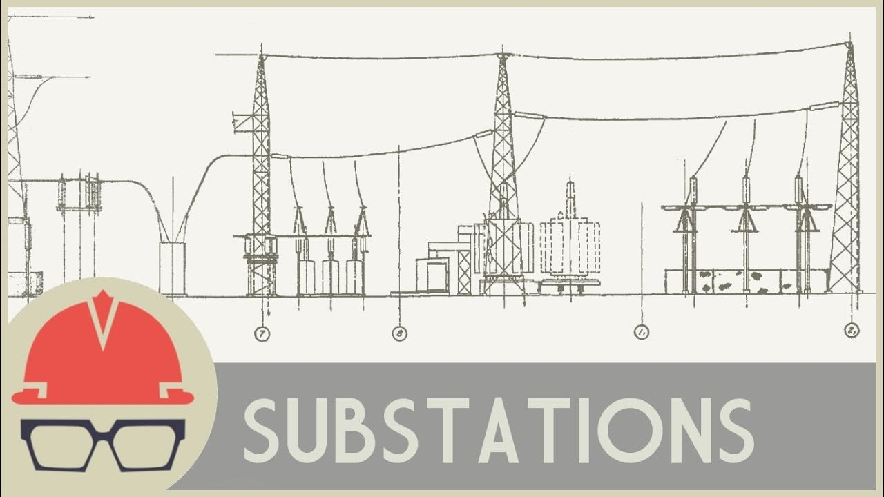
คำอธิบายเชิงปฏิบัติทางวิศวกรรมเชิงลึกนี้ให้ข้อมูลพื้นฐานเกี่ยวกับสถานีจ่ายไฟ หม้อแปลง และอุปกรณ์ควบคุมไฟฟ้า เป็นบริบทเพื่อการศึกษา ไม่ใช่คำแนะนำในการเปลี่ยนสวิตช์หรือการทดสอบ.
คำถามที่มักถูกถาม
ขั้นตอนแรกคืออะไร?
Define the exact transient recovery voltage circuit breaker boundary, equipment identity and operating state before comparing a value or feature.
หน้าแคตตาล็อกสามารถแทนที่วิศวกรโครงการได้หรือไม่
ไม่ ไม่ได้ มีหน้าผลิตภัณฑ์ที่เชื่อมโยงระบุถึงกลุ่มอุปกรณ์ของ Shenheng ที่เกี่ยวข้อง โดยรุ่นที่จัดส่ง อุปกรณ์เสริม มาตรฐาน และแผนการรับรองโครงการเป็นสิ่งที่ควบคุมผลการตัดสินใจในขั้นสุดท้าย.
หลักฐานใดควรถูกเก็บรักษาไว้?
เก็บรูปวาด การคำนวณ หรือวิธีการทดสอบที่ได้รับการอนุมัติ พร้อมกับค่าการวัดที่ได้จากเครื่องมือ ภาพถ่าย รายละเอียดของเครื่องมือ ข้อผิดพลาด การตั้งค่า และบันทึกผลการก่อสร้างที่ได้ในที่สุด.
บทความนี้อนุญาตให้ทำงานแบบสดได้หรือไม่
ไม่ ท่านต้องมีบุคลากรที่มีคุณสมบัติเหมาะสมปฏิบัติตามหลักการความปลอดภัยด้านไฟฟ้าของไซต์งาน รวมถึงคำแนะนำของผู้ออกแบบและผู้ผลิต.