Shenheng Power Equipment Co., Ltd.
- Home
- Products
Products
Since 2001, Shenheng Power has been a trusted manufacturer of power transmission and distribution equipment, delivering reliable electrical solutions globally.

- Solutions
- News & Blog
- Service
- About Us
- Contact Us
Since 2001, Shenheng Power has been a trusted manufacturer of power transmission and distribution equipment, delivering reliable electrical solutions globally.
Transformer turns ratio test results interpretation compares measured ratios, phase relationships and excitation behavior with nameplate vector-group data, tap position and a verified baseline. The practical objective is not to complete a calendar checkbox or collect an isolated number. It is to produce reliable evidence that supports a safe decision: continue in service, correct a defined defect, monitor a trend, or escalate the equipment for engineering review.
This guide is written for owners, EPC teams, maintenance planners, commissioning engineers and procurement staff working with oil-immersed power transformer. It explains scope, preparation, field execution, interpretation and reporting. It does not replace the equipment manual, the project specification, an approved switching program or the judgment of qualified electrical personnel.
The condition of primary electrical equipment changes through loading, switching duty, thermal cycling, moisture, contamination, vibration, transport and maintenance history. A disciplined transformer turns ratio test results interpretation process converts those influences into observations that can be compared over time. That comparison is usually more valuable than a generic pass value copied from another voltage class or another design.
The task also creates a common record for different teams. Operators can connect alarms and events with physical findings; engineers can compare phases, compartments or previous tests; procurement teams can specify test access and documentation for new equipment. The result should always state what was examined, what was not examined and which rule was used to make the decision.
Start with the decision the work must support. Acceptance testing after installation, a routine condition assessment, post-maintenance verification and investigation after an abnormal event are different jobs. They may use similar instruments, but they need different boundaries, comparison data and follow-up actions.
Identify the exact asset and configuration from approved drawings and nameplate data. Record voltage class, rating, manufacturer, model, serial number, location, tap or breaker position, protection arrangement and connected equipment. Review previous findings, fault history, loading, recent switching, transport or repair work, and outstanding defects. If a comparable baseline does not exist, label the new result as the first baseline rather than presenting it as a trend.
Agree on the acceptance reference before the outage or survey. It may be a manufacturer limit, project specification, owner procedure, applicable standard or an engineering comparison with equivalent phases and historical results. Where these references differ, record the governing document and edition. Do not invent a universal limit for equipment whose design and test method have not been confirmed.
Electrical work must be planned and performed by qualified people. Identify every normal, alternate, induced and stored-energy source. Apply the site switching, lockout, isolation, absence-of-voltage verification and grounding process appropriate to the task. Control adjacent energized equipment and maintain required approach boundaries. A test instrument does not make unsafe access acceptable.
Some diagnostic methods intentionally energize a winding or store energy in capacitive or inductive circuits. Others are non-contact surveys performed on in-service equipment. The work instruction must clearly distinguish these conditions. Confirm instrument rating, lead condition, protective features, calibration status and discharge procedure. Before changing a connection, verify that stored energy has been safely removed and protective grounds are restored as required.
Stop-work criteria belong in the plan. Unexpected sound, odor, pressure, oil release, smoke, abnormal mechanism movement, unstable readings or a conflict between drawings and the actual equipment should trigger a pause. Preserving evidence and asking for engineering review is safer and more useful than forcing the procedure to completion.
Use a prepared data sheet and capture raw observations at the time of work. Record operating condition, load where relevant, ambient temperature, equipment temperature, humidity, weather, test voltage or current, lead arrangement, instrument range and elapsed time. Photographs should show context and test points without exposing confidential or unreadable nameplate details.
Repeatability is a quality check. When a value or pattern appears unusual, first check asset identity, instrument zero or self-test, lead contact, sensor position, selected range and equipment state. Repeat using the same controlled setup. Do not repeatedly operate a mechanism or apply additional electrical stress when active damage is suspected.
| Observation or review point | What it may indicate | Practical response |
|---|---|---|
| All phases close to expected ratio | Connections and turns relationship are consistent | Confirm against project or manufacturer tolerance |
| One phase differs | Possible lead error, winding issue or tap contact problem | Reconnect and repeat before escalation |
| All phases shift similarly | Wrong tap, wrong voltage basis or nameplate entry | Verify calculation and tap position |
| Ratio normal but excitation abnormal | Core condition, magnetization or connection issue may remain | Use complementary tests and engineering review |
Interpretation should move from data quality to equipment condition. First ask whether the observation is real and reproducible. Then compare equivalent phases, identical compartments, previous records, factory results and the manufacturer’s expected pattern. Finally, consider the operating context: loading, temperature, humidity, tap position, control voltage, recent faults and maintenance can all change a reading without representing the same failure mechanism.
Separate observation from diagnosis. “The center phase is warmer than the outer phases under similar current” is an observation. “A loose connection is confirmed” is a diagnosis that may require inspection, resistance measurement or other evidence. Reports that keep this distinction clear are easier to review and less likely to cause unnecessary outages or missed defects.
Use complementary evidence when the consequence is significant. Visual condition, thermography, electrical test results, oil analysis, protection records, operating history and mechanical traces answer different questions. Agreement among independent methods increases confidence. A contradiction should be investigated rather than averaged away.
Every finding needs a disposition. Useful categories include acceptable for service, monitor at a defined interval, correct before energization, investigate during the next planned outage, or remove from service for urgent engineering assessment. Assign an owner and due date. If corrective work is performed, preserve both as-found and as-left data rather than replacing the original record.
Set the next interval from risk. Consider asset criticality, duty, environment, age, previous defects, spare availability and consequence of failure. A stable low-risk asset may stay on the normal program; adverse trends, severe contamination, repeated operations or a fault event may justify earlier targeted work. Document the reason so the next planner understands the decision.
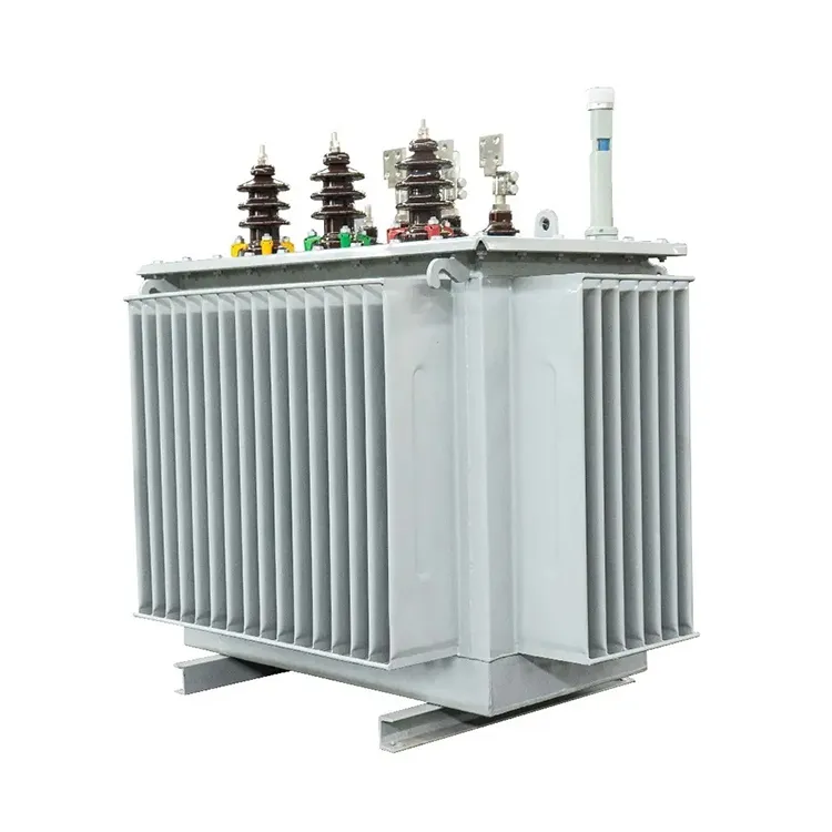
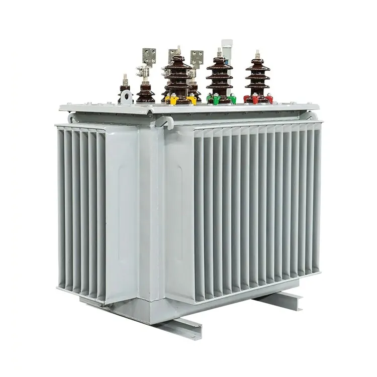
New projects can make future maintenance safer and faster by defining access, isolation points, test terminals, sensors, viewing windows, lifting arrangements, documentation and baseline data during procurement. The configuration of Shenheng’s oil-immersed power transformer should be reviewed against the project single-line diagram, environment, protection philosophy and maintenance capability. Final ratings and features must always be confirmed in the approved technical offer.
The broader transformer turns ratio test provides the parent procedure for this topic. Keeping the new page focused on transformer turns ratio test results interpretation prevents it from competing with the broader guide while strengthening the same technical cluster.
Identify the project, site, asset, manufacturer, model, serial number, ratings, location and tested boundary. State the purpose, governing procedure and reference documents. Record instrument make and model, serial number, calibration due date, accessories, test or survey configuration, operating state and environmental conditions.
Present raw results before corrected or calculated values. Include trace files, thermal and visible images, connection diagrams and exceptions where relevant. Explain every correction and assumption. The conclusion should list observed facts, acceptance basis, interpretation, limitations, recommended actions, responsible owner and required completion date. Attach the as-left verification after repairs.
Use the editions and requirements named by the project and equipment manufacturer. These neutral resources are starting points for electrical safety, maintenance standards and calibration traceability:
Transformer turns ratio test results interpretation compares measured ratios, phase relationships and excitation behavior with nameplate vector-group data, tap position and a verified baseline.
The answer depends on the method. Non-contact observation may be designed for in-service equipment, while connection, internal inspection, adjustment and most electrical tests require isolation. Use the approved site procedure and qualified personnel.
No. First verify asset identity, configuration, instrument, connection, environmental condition and repeatability. A persistent abnormal pattern should be assessed with manufacturer guidance, history and complementary evidence.
Record the asset, purpose, method, instrument and calibration status, operating or isolated condition, environment, raw findings, photographs or traces, acceptance basis, defects, actions and as-left condition.
A strong transformer turns ratio test results interpretation program is therefore a repeatable decision process. It protects people first, preserves trustworthy evidence and connects each observation to a practical maintenance or commissioning action.