Shenheng Power Equipment Co., Ltd.
- Home
- Products
Products
Since 2001, Shenheng Power has been a trusted manufacturer of power transmission and distribution equipment, delivering reliable electrical solutions globally.

- Solutions
- News & Blog
- Service
- About Us
- Contact Us
Since 2001, Shenheng Power has been a trusted manufacturer of power transmission and distribution equipment, delivering reliable electrical solutions globally.
A transformer polarity test identifies the relative instantaneous direction of voltage in two windings. On a single-phase transformer, a controlled AC source and three voltage measurements show whether the windings are additive or subtractive at the selected terminals. On three-phase units, polarity is only one part of the required connection check; phase sequence, angular displacement, terminal markings, and vector group must also be verified. The test should be performed only on an isolated, de-energized transformer by qualified personnel following the manufacturer’s diagram and an approved low-voltage procedure.
Polarity tells engineers which winding terminals have the same instantaneous voltage sense. That information controls how coils and transformers can be connected. A wrong assumption can create opposing or reinforcing voltages where they were not intended, cause circulating current in parallel units, reverse measurement direction, or produce an incorrect three-phase vector relationship.
Terminal markings provide the design reference, but a field test verifies the physical relationship after manufacture, repair, transport, or reconnection. IEEE C57.12.70 describes standard terminal markings, additive and subtractive polarity, transformer connections, and phase displacement. The ordered standard, nameplate, winding diagram, and factory report remain the controlling documents for a specific transformer.
For the familiar single-phase AC method, one terminal from the high-voltage winding is temporarily connected to one terminal from the low-voltage winding. A low test voltage is applied to one winding. The voltage measured across the two remaining free terminals is then compared with the separately measured winding voltages.
This is a relationship between the selected terminals, not a statement that one transformer type is universally “better.” Never assume the expected result from physical terminal location alone. Use the approved diagram and instrument method.

| Test objective | Required information | Evidence to retain |
|---|---|---|
| Verify a single-phase winding relationship | Winding diagram, terminal IDs, safe test voltage | Three measured voltages and connection sketch |
| Confirm repaired winding terminals | Repair report and factory markings | Before/after terminal map and test result |
| Prepare units for parallel operation | Ratio, impedance, polarity, phase displacement | Complete comparison reviewed by an engineer |
| Check a three-phase transformer | Vector group, phase sequence, angular displacement | Phase-by-phase ratio and vector-group record |
The following sequence explains the logic for planning. It is not an instruction to work on energized power equipment.
Assume the applied winding measures 100.0 V and the induced winding measures 10.0 V. If the voltage across the selected free terminals is close to 110.0 V, those terminals are in an additive series relationship. If it is close to 90.0 V, they are in a subtractive relationship. The objective is the relationship, not perfect arithmetic: supply fluctuation, meter uncertainty, and transformer regulation can introduce small differences.
Do not use these example voltages as a universal field setting. The test voltage and connection must come from the transformer and test-equipment procedures. A power transformer also requires checks beyond this simple demonstration.
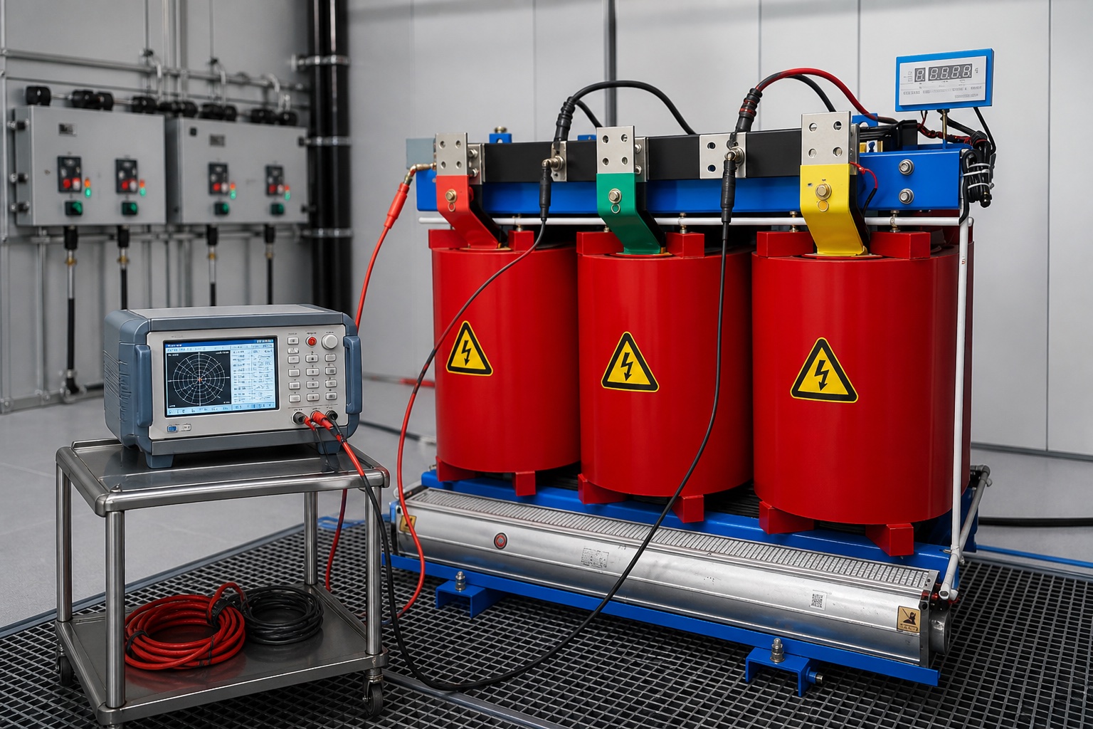
A three-phase nameplate such as Dyn11 conveys winding connections and angular displacement, not merely additive or subtractive polarity. Each phase must have the correct internal relationship, the external terminals must be correctly marked, and the phase sequence must agree with the system. A simple single-phase sum/difference check cannot fully prove those conditions.
A three-phase ratio test set can apply low voltage in a controlled sequence and report ratio, phase angle, and connection. Results should be compared with the approved vector group and factory data. This NPTEL transformer testing lecture material provides a neutral theoretical reference for polarity testing.
Polarity answers a narrow connection question. A transformer turns ratio test verifies the winding voltage relationship and often phase angle. Winding resistance testing evaluates DC resistance and connection continuity. Insulation tests assess dielectric condition. Excitation-current, impedance, oil, thermal, and protection checks address other failure modes.
For parallel operation, matching polarity is necessary but not sufficient. Voltage ratio, tap setting, phase sequence, vector group, impedance, frequency, and system protection must all be compatible. Shenheng’s guide to transformer impedance and parallel operation explains why units can share load poorly even when their polarity is correct.
Record the transformer ID, serial number, winding diagram revision, nameplate photograph, terminal designations, tap position, test source, meters and calibration dates, connection sketch, applied and induced voltages, series voltage, expected relationship, result, date, ambient condition, personnel, and reviewer. For three-phase units, add phase sequence, ratio and angle results for each phase, and the verified vector group.
If the series voltage does not resemble the expected sum or difference, stop and preserve the as-found setup. Confirm source stability, meter ranges, temporary links, disconnected external circuits, and tap position. Repeat only after documenting a justified correction. If the anomaly remains, compare ratio, winding-resistance, and phase-angle results and consult the responsible engineer. Do not relabel terminals merely to make the result agree with an assumption.
For repaired or older equipment, drawings and physical labels can conflict. Resolve the discrepancy through a controlled terminal-identification plan before connecting the transformer to a bus, and retain the evidence establishing the final approved designations.
When ordering a transformer, request the terminal diagram and factory routine-test report early enough for protection and cable-design review. Product-specific details can be discussed for Shenheng’s 35 kV oil-immersed power transformer or cast-resin dry-type transformer; the final site procedure must follow the ordered configuration.
Acceptance boundary: This article explains the measurement logic, not a universal acceptance procedure. The transformer manufacturer, project specification, governing standard, and responsible engineer determine the applied test voltage, permitted connections, tolerances, and required companion tests. Stop work when the transformer identity, terminal markings, isolation, or expected vector relationship is uncertain. A complete record should allow a second qualified reviewer to reconstruct the setup without relying on memory.
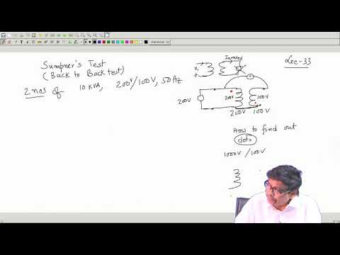
This lecture demonstrates polarity and Sumpner-test theory for electrical-machine students. Site testing still requires a project-specific method and qualified personnel.
No. Polarity describes the relative instantaneous winding voltage direction. Phase sequence describes the order of three phases. Both matter on three-phase systems.
A meter is only one part of a controlled setup. Isolation, a suitable low-voltage source, rated leads, documentation, barriers, and a qualified procedure are also required.
Incorrect polarity or phase relationship can oppose voltages or drive damaging circulating current. Ratio, vector group, phase sequence, and impedance must also be compatible.
It is commonly verified after work that may affect winding leads or terminal markings. The repair and manufacturer test plan determines the complete scope.
A suitable modern ratio test set may report polarity and phase angle, but the approved procedure must specify how the connection is verified and documented.