Shenheng Power Equipment Co., Ltd.
- Home
- Products
Products
Since 2001, Shenheng Power has been a trusted manufacturer of power transmission and distribution equipment, delivering reliable electrical solutions globally.
- Solutions
- News & Blog
- Service
- About Us
- Contact Us
Since 2001, Shenheng Power has been a trusted manufacturer of power transmission and distribution equipment, delivering reliable electrical solutions globally.
An MV switchgear secondary control plug replacement needs more evidence than a matching shell and pin count. Verify the exact breaker and cell, connector identity, contact assignments, control supply, mechanical engagement and affected interlocks against approved drawings. Then require a manufacturer-approved replacement scope and documented functional acceptance before service. A connector that physically fits can still connect a trip coil, indication or permissive incorrectly. This guide helps owners and buyers define a replacement review; it is not a live-work instruction, universal pinout or permission to modify an installed switchgear assembly.
Related background: Medium Voltage Switchgear: Components and Selection
The secondary interface carries control and auxiliary functions associated with a withdrawable circuit breaker. Depending on the assembly, those functions can include closing and tripping circuits, spring-charging power, status indication and interlocking signals. The actual wiring diagram determines what passes through a particular connector. Do not assume that every signal listed in a catalog crosses the plug on the unit being repaired.
Separate the removable half, fixed half, associated wiring harness and mounting parts in the work scope. A damaged contact may be one symptom of misalignment or strain rather than an isolated consumable failure. Ask the manufacturer whether a contact, connector half, harness or coordinated assembly should be replaced. An unapproved partial repair can preserve the cause of the original damage.
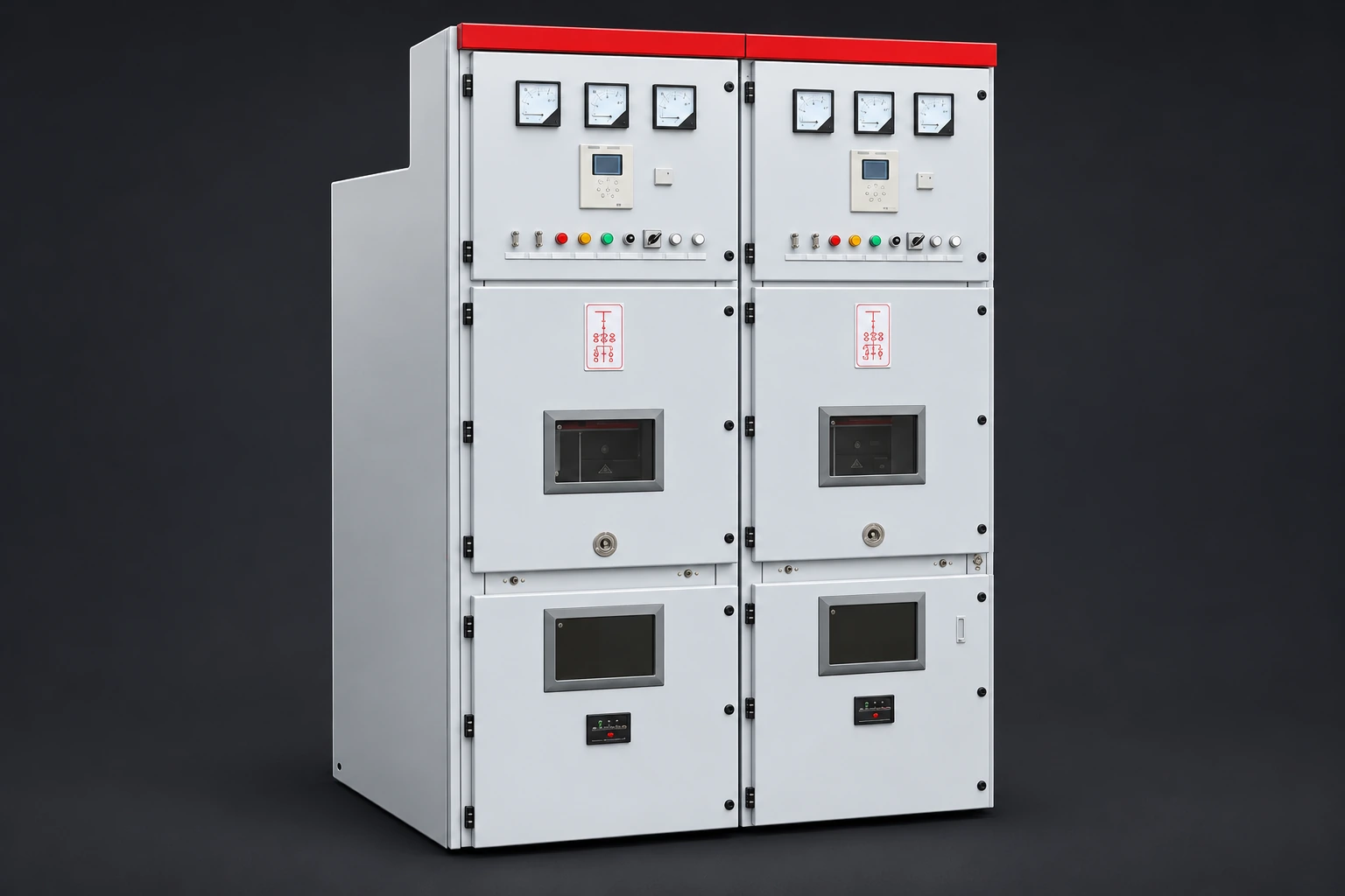
The Shenheng medium voltage switchgear product provides the equipment-family context. Its external appearance does not establish the secondary connector model or internal wiring of an installed panel. Request serial-specific drawings and parts information for the supplied assembly. Do not infer an insulation system, interlock sequence or interchangeable breaker family from a product title alone.
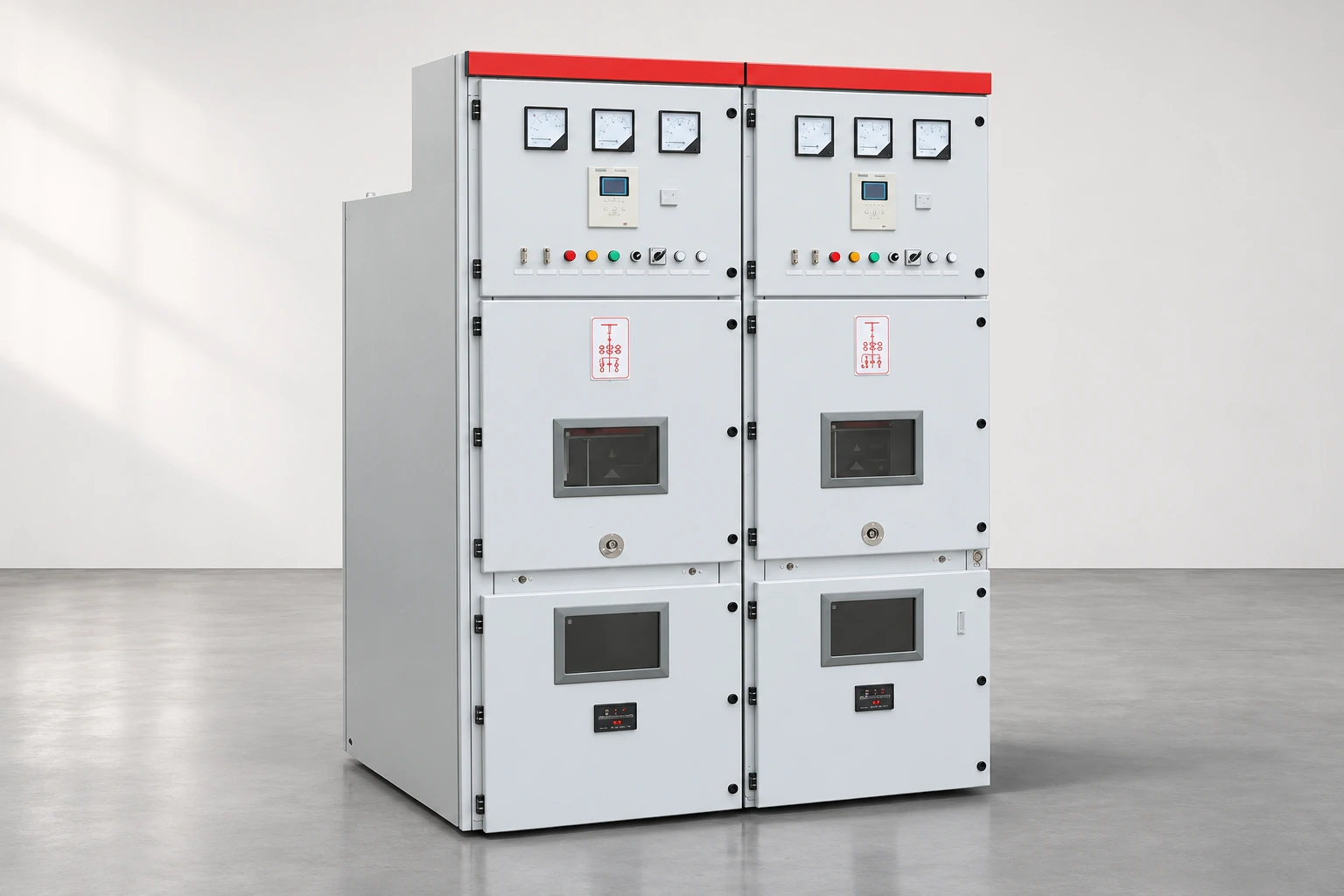
Mechanical keying helps prevent incorrect engagement, but it does not prove circuit equivalence. Similar housings can be wired for different control voltages, operating mechanisms or project functions. Even equipment with the same broad model designation may have project-specific auxiliary arrangements. A spare from a neighboring panel is therefore not approved simply because it can be inserted.
The Sydney Water HV switchgear technical specification includes requirements for auxiliary-circuit arrangements, draw-out positions, interlocks and functional testing. It is a utility’s project specification, not a universal replacement procedure or evidence that a Shenheng assembly complies with that project. It illustrates why a replacement review must cover the complete function rather than the connector body alone.
Use the approved schematic revision as the reference. If the actual wiring differs, stop the substitution decision and resolve the discrepancy through the responsible engineering authority. Do not create a guessed cross-reference based only on wire colors, contact numbering conventions or a photograph of a different cell.
The matrix below is an owner’s purchasing and review checklist. Its acceptance evidence must be completed for the actual equipment; it does not provide ratings or a wiring recipe.
| Review item | Evidence to request | Reason to hold approval |
|---|---|---|
| Equipment identity | Panel, cell, breaker and serial references | Spare is described only by a general switchgear name |
| Connector identity | Approved part number, revision and mating-half reference | Shell fits but manufacturer approval is missing |
| Circuit assignments | Contact-to-terminal schedule matched to schematic | Pin count is the only electrical comparison |
| Electrical duty | Applicable control supply and circuit duty from approved data | Ratings are inferred from a similar-looking plug |
| Mechanical interface | Mounting, alignment, engagement and retention information | Visible wear or forced engagement remains unexplained |
| Functional scope | Test plan for affected commands, indications and interlocks | Continuity alone is proposed as final acceptance |
| Records | Drawing updates, parts traceability and signed results | Changed wiring would remain undocumented |
Ask the supplier to identify what is excluded. A quote for a loose connector may not include terminal hardware, contact extraction tools, harness support or manufacturer attendance. Resolve those boundaries before an outage is booked. A low unit price is not a useful comparison if another quotation includes the engineering verification needed to return the assembly to service.
Build the review schedule from the unit’s approved documents. Each used contact should connect to an identifiable circuit function and drawing reference. Where spare contacts exist, preserve the documented spare status rather than assuming they can be reassigned. Distinguish supply circuits from dry contacts, indications and any other interfaces identified by the designer.
Check both sides of the interface. A drawing for the breaker harness is incomplete if the fixed-cell side uses a different revision. Likewise, a correct fixed plug does not repair an incorrectly modified breaker. Record any earlier retrofit affecting protection, closing permissives, remote commands or supervision so that the replacement is checked against the present approved configuration.
The trip circuit supervision article explains a related monitoring function. Supervision can indicate certain circuit problems, but a healthy indication is not evidence that every connector contact and control function is correct. A replacement review should identify what the supervision scheme covers and what requires a separate functional test.
The meanings of service, test, disconnected and removed positions depend on the assembly design and operating documentation. Do not assume that a test position disconnects all auxiliary energy. Secondary interfaces may remain engaged in positions where primary contacts are separated. The approved operating manual must explain the actual arrangement.
For the replacement review, list the positions in which engagement, withdrawal or command functions are permitted. Ask how the connector retention and mechanical interlocking relate to those positions. Testing should demonstrate the specified behavior without bypassing safeguards. A cable extension or temporary test plug should be used only within an approved arrangement, not improvised to avoid a difficult engagement problem.
The earthing-switch interlock guide covers a separate but connected safeguard. Keep the control plug review focused on the circuits and mechanisms it affects. Do not claim that replacing a secondary plug verifies the complete earthing system, shutter mechanism or primary isolation arrangement.
A technically suitable part does not make the replacement task safe. Qualified personnel need the site procedure, equipment instructions, defined work boundary and control of all relevant energy sources. Stored mechanical energy and separately supplied auxiliary circuits also require attention. Selecting a spare and authorizing the work are distinct decisions.
The HSE guidance on electrical safe working practices provides a general safety framework. It does not establish a connector-specific replacement sequence. The site’s applicable law and authorized procedure govern the task. Keep the article’s review matrix in the procurement file; do not use it as a field switching instruction.
When damage suggests overheating, tracking, broken insulation or repeated misalignment, preserve the evidence and refer the cause to the appropriate specialist. Replacing the visible damaged part without reviewing the mating surface and associated mechanism may lead to recurrence. Photographs taken under the authorized safe-work process can support identification, but should not replace part numbers or inspection records.
Agree a written acceptance plan proportionate to the change. It should identify the affected circuits, equipment state, expected responses, responsible personnel and evidence to retain. This can include inspection of engagement and retention, verification against drawings, and functional demonstration of the authorized command and indication paths. The manufacturer and responsible engineer decide the actual test methods and limits.
Do not prescribe a generic insulation-test voltage across connected electronic equipment. Instruments and auxiliary devices can have specific restrictions. The approved procedure must identify what is disconnected, protected or excluded and how the final configuration is restored. A successful continuity reading cannot demonstrate command logic, correct indication or all interlock functions.
Use the switchgear factory acceptance checklist as broader background for organizing evidence. A field replacement is not automatically a repeat factory acceptance test, and a limited repair test is not proof that the complete original design has been reassessed. State the tested scope accurately in the final record.
Send the manufacturer the assembly and breaker identification, existing connector references, approved drawing revisions, description of damage and the requested replacement boundary. Include the required delivery date and outage constraints, but avoid requesting an unsupported emergency substitute. Ask for written compatibility confirmation and a list of documents, parts and services included in the quotation.
Before purchase approval, reconcile exceptions. If the original part is obsolete, ask whether the proposed change affects both connector halves, harnesses, mounting, drawings or functional testing. Keep the original approval and any engineering deviation together. After installation, update the parts register and drawings so a later technician does not order against the superseded configuration.
Close the work only after the approved acceptance results and as-left configuration are recorded. A replacement should leave the owner with a known interface and an evidence trail, not merely a connector that can be pushed into place.
This US Department of Labor training discusses hazardous energy control. It supplies safety context, not a switchgear-specific operating or replacement sequence.
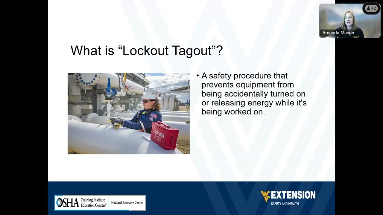
Further learning: Stand Up For Safety and Health – Lockout tagout — USDepartmentofLabor. Open the video on YouTube.
This government training introduces the energy-control context for maintenance. It does not authorize work on this switchgear or define the isolation sequence for a particular panel.
No. Confirm part identity, circuit assignments, electrical duty, mounting, retention and affected functions against approved unit-specific documentation. Pin count describes only one feature and does not establish electrical interchangeability.
Only if the manufacturer and responsible engineering authority approve the specific substitution and acceptance scope. Similar appearance or successful physical engagement does not prove that the donor part matches the receiving cell and breaker configuration.
No. It demonstrates only the coverage of the actual supervision arrangement. Other contacts, closing circuits, indications and mechanical functions may require separate checks under the approved test plan.
Retain part traceability, compatibility approval, the applicable drawing revisions, the reason for replacement, inspection findings, functional results and the final configuration. Record any approved deviation so the next spare order uses the correct information.