Shenheng Power Equipment Co., Ltd.
- Home
- Products
Products
Since 2001, Shenheng Power has been a trusted manufacturer of power transmission and distribution equipment, delivering reliable electrical solutions globally.
- Solutions
- News & Blog
- Service
- About Us
- Contact Us
Since 2001, Shenheng Power has been a trusted manufacturer of power transmission and distribution equipment, delivering reliable electrical solutions globally.
Dry type transformer replacement temperature sensor compatibility depends on the sensor technology, resistance characteristic, wiring arrangement, controller input and approved installation. A probe that fits an opening is not necessarily compatible with the existing monitoring and protection system. Identify the supplied sensor and controller from serial-specific records, then obtain manufacturer approval for the replacement and its functional checks. Do not substitute a Pt100, Pt1000, thermistor or thermocouple merely because it has similar leads. This guide is a purchasing and engineering review framework; it does not authorize opening an energized transformer, altering embedded winding insulation or choosing new alarm and trip settings.
Collect the transformer serial number, sensor part reference, controller model and drawing revision. Record which channels monitor windings, the core or another location, and which outputs operate cooling, alarms or shutdown. Those functions must come from the supplied documentation; they cannot be established from the number of displays on the front panel.
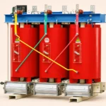
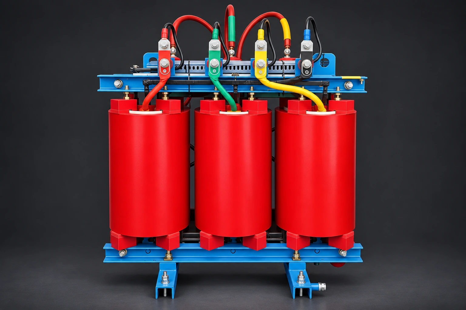
The Shenheng cast resin dry type transformer illustrates the relevant product family. Its visible coils and terminals do not reveal the embedded sensor technology, lead arrangement or approved replacement method. Ask for the documentation of the actual supplied unit. The generated product illustrations in this article do not depict a sensor extraction procedure or show verified internal sensor positions.
If records disagree with the installation, have the manufacturer and responsible engineer reconcile them before ordering. A previous controller retrofit may mean that an old spare-parts list no longer describes the current arrangement. Equally, an unlabeled spare in a stores bin is not identified simply because its cable color resembles the installed cable.

A resistance temperature detector uses a defined resistance relationship to support temperature measurement. The NIST explanation of platinum resistance thermometers describes this principle and notes practical effects associated with leads and sensor construction. That measurement principle does not establish the suitability of a particular transformer spare.
Thermistor-based protection may instead use a characteristic evaluated by a dedicated relay. The exact device and controller determine how the signal is interpreted. A positive temperature coefficient as a material property does not make every sensor with that description interchangeable. Confirm the actual characteristic and intended input rather than relying on an abbreviation in a sales listing.
The IEC 60751 publication scope covers industrial platinum resistance thermometers and platinum temperature sensors, including the resistance-temperature relationship. It is useful for defining what platinum sensor data should reference. The public scope is not a transformer installation procedure, and this article does not claim to have checked every requirement in the full standard.
Treat the sensor, leads, input channel, configured interpretation and output action as one review chain. A replacement can appear plausible at room temperature while failing to provide the required response over the operating range or under a sensor fault. A single displayed value therefore cannot close the compatibility review.
| Item to verify | Evidence for the actual replacement | Approval concern |
|---|---|---|
| Sensor technology | Exact sensor and input type in approved documentation | Different technologies treated as plug-compatible |
| Characteristic | Nominal resistance and applicable characteristic or threshold specification | Generic “temperature sensor” description only |
| Leads and terminals | Approved wire arrangement and terminal schedule | Wire color or cable length used as the sole identity check |
| Mechanical installation | Dimensions, location and manufacturer replacement method | A fit is achieved by modifying winding insulation |
| Environmental suitability | Approved sheath, lead insulation and service conditions | An exposed general-purpose probe replaces a specified assembly |
| Controller configuration | Correct channel selection, mapping and approved settings | Plausible display accepted without checking input selection |
| Functional response | Agreed verification of measurement, alarm, cooling and protection interfaces as applicable | Only the sensor continuity is checked |
This is an owner’s qualitative comparison table. Obtain values and acceptance limits from the manufacturer and approved project documents. It supplies no universal winding temperatures, sensor test voltages or trip settings.
Two-wire, three-wire and four-wire measurements use different arrangements to address the relationship between sensor resistance and lead resistance. NIST notes that lead compensation matters for common industrial platinum thermometer configurations. Follow the controller’s exact terminal diagram and the approved sensor wiring arrangement rather than adapting the connection by guesswork.
Do not identify leads by color alone. Confirm cable identifiers, terminal numbers and the manufacturer’s reference. Repairs, extensions and earlier retrofits can introduce changes that are not visible at the sensor end. Ask whether an extension or replacement harness is permitted, what materials are required and what evidence should be retained.
A loose connection, damaged lead or controller configuration problem can resemble a failed sensor. Diagnose the cause using the authorized procedure before assuming that the embedded sensing element must be replaced. This avoids ordering the wrong component and reduces the temptation to bypass a troublesome protection channel while waiting for parts.
Some sensors may be installed in accessible provisions; others may be integrated into the winding construction. Do not assume every dry type transformer has a removable probe pocket. The transformer manufacturer must identify whether field replacement is allowed and which method preserves the insulation system and sensing location.
A surface-mounted substitute can measure a different thermal condition from an embedded winding sensor. A neat installation does not prove that it will support the same protective function. If the original sensor cannot be replaced as supplied, obtain a documented engineering solution that addresses sensing location, response, protection and acceptance. A general-purpose adhesive probe is not automatically an equivalent repair.
Keep the supplied geometry intact unless a specifically approved modification is required. Drilling, cutting or forcing a new probe into the coil structure is outside a simple spare-parts substitution. Arrange manufacturer involvement early when access is uncertain so that the outage and repair quotation reflect the actual scope.
Record the existing channel configuration before a change. Confirm which sensor each channel represents and which outputs it influences. Where a controller supports multiple input technologies, its capability alone does not show that the correct option is selected. The approved setup must match the installed sensor and intended function.
The temperature monitoring guide explains the wider monitoring arrangement. Use it to distinguish measurement from alarm and protection decisions, then return to unit-specific instructions for the replacement. A familiar front-panel display does not prove equivalence between two controller versions.
Keep alarm and trip settings under the responsible engineer’s control. Replacing a sensor is not permission to increase a setting to suppress nuisance alarms. If a controller is replaced at the same time, verify the output logic, power supply and external interface under an approved test plan. A matching sensor input does not establish compatibility of every relay contact or communications function.
Where the installed system uses temperature signals for fans, confirm which input and output channels perform that task. A sensor fault may affect cooling control differently from the protective trip path. The approved documentation should explain both the intended normal response and response to detected sensor problems.
The dry type transformer fan control article addresses cooling logic, while the replacement cooling fan review addresses fan hardware. Those are complementary topics; neither supplies sensor compatibility evidence. Keep their records linked if a common controller replacement affects all three functions.
Do not infer a higher transformer rating from a new sensor or a controller with more features. Thermal capability depends on the approved transformer design, cooling arrangement and installation conditions. A replacement monitoring component can help restore intended operation but does not itself establish new loading capability.
Agree the scope of inspection and functional verification, the responsible personnel and the records required. The plan should address the identified fault, correct replacement identity, lead and channel mapping, plausible measurement behavior and the affected outputs. Where a simulated input or reference instrument is used, follow the manufacturer’s method and limits.
Do not apply an improvised high-voltage insulation test to a connected sensor or controller. Measurement and electronic protection circuits can require particular disconnection or protection arrangements. The authorized procedure must explain the equipment state and how the final configuration is restored. This guide intentionally provides no field test recipe.
Document what was verified and what remains dependent on supplied design information. A bench calibration of a spare does not prove its installed sensing location or the complete trip path. Likewise, a successful alarm demonstration does not establish the full temperature accuracy of every channel. Match the acceptance statement to the evidence actually collected.
Provide the manufacturer with the transformer and controller identifiers, sensor reference, circuit drawing, channel function, observed symptom and any approved inspection findings. Ask whether the proposed part is an exact spare or an engineered alternative. Request the installation method, configuration requirements, acceptance scope and any limitations that affect warranty or maintenance planning.
Ask the supplier to state whether the price covers only the sensing element or also its lead assembly, connectors and service support. If an alternative is proposed, request a comparison against the original characteristic, physical installation and controller interface. Resolve exceptions before delivery so that the repair team does not discover a missing approval during the outage.
After acceptance, update the parts register, drawings and configuration record. Retain the reason for replacement and the as-left channel mapping. The next review should be able to distinguish a sensor change from a controller retrofit without depending on the memory of the person who completed the repair.
This NPTEL IIT Guwahati lecture explains resistance temperature detectors, thermistors and thermocouples. It supplies sensor principles, not approval of any transformer replacement part.
Further learning: Lec 25 : Thermostatic temperature, Resistance Temperature Detectors(RTD), Thermistors, Thermocouples — NPTEL IIT Guwahati. Open the video on YouTube.
This university lecture explains temperature sensing technologies. It supplies learning context for distinguishing inputs, not approval of a transformer spare or a procedure for work on installed equipment.
Do not assume interchangeability. Confirm the original characteristic, controller input and intended protective function. A different sensor technology needs an approved engineering review of the complete sensing and output chain, not only a matching mechanical size.
No. Verify the specified characteristic, wiring, configuration, installation and affected functional responses. One plausible reading does not demonstrate performance across the required range or the response to a failed sensor.
No general assumption is safe. The manufacturer must identify whether the supplied construction permits replacement and what method preserves insulation and sensing location. An accessible surface does not prove that the original sensing element is removable.
Keep transformer and controller identity, sensor part reference, approved alternative details if any, drawing revision, lead arrangement, channel mapping, configuration and acceptance results. Record the repair scope so later orders do not repeat an obsolete arrangement.