Shenheng Power Equipment Co., Ltd.
- Home
- Products
Products
Since 2001, Shenheng Power has been a trusted manufacturer of power transmission and distribution equipment, delivering reliable electrical solutions globally.
- Solutions
- News & Blog
- Service
- About Us
- Contact Us
Since 2001, Shenheng Power has been a trusted manufacturer of power transmission and distribution equipment, delivering reliable electrical solutions globally.
MV switchgear trip circuit supervision monitors the electrical path needed to operate a circuit breaker’s trip coil and raises an alarm when the monitored path becomes unhealthy. Its coverage depends on the actual wiring, breaker position, auxiliary contacts, supply arrangement and relay configuration. A healthy indication is useful evidence, but it does not prove that the breaker mechanism will operate or that every protection function will issue the correct command. Before specifying or accepting supervision, define which paths and operating states must be covered. This guide explains the engineering review and acceptance evidence; it is not a wiring recipe or a live troubleshooting procedure.
Related background: Medium Voltage Switchgear: Components and Selection
A typical electrically operated breaker relies on several connected functions: a source of control energy, circuit protection and isolation devices, protection or control contacts, wiring and terminals, and the breaker trip coil. The exact arrangement varies by design. Supervision can help reveal an interrupted monitored path before a real power-system fault makes the failure apparent. It cannot compensate for an incomplete protection design or an unmaintained mechanism.
For a project using medium voltage switchgear, request the approved control schematic for the actual panel and breaker combination. A generic brochure may show that supervision is available without showing how it is implemented in the ordered equipment. Confirm the supervision device or relay function, its inputs, the monitored coil and the alarm destination. Equipment labels and drawing references should make those relationships clear.
Keep the scope distinct from circuit breaker failure protection. Failure protection addresses the consequences of a breaker failing to clear after a trip command according to its designed logic. Trip circuit supervision addresses the health of the monitored circuit. Both may exist in a protection system, but naming one does not establish the presence or adequacy of the other.
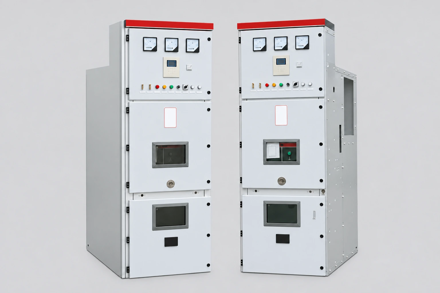
An indication that a DC distribution board is energized does not necessarily establish continuity through a particular breaker trip coil. Similarly, a numerical relay reporting normal internal operation does not automatically prove that its output wiring and the breaker circuit are healthy. Write these as separate functions in the specification, with separate evidence where the design requires it.
Rodney Hughes’ technical explanation of trip circuit monitoring describes different degrees of coverage, including supply health and wiring continuity in different breaker positions. It also explains an important limitation: monitoring the circuit does not prove operation of the protection device’s trip contact. The detailed circuit arrangement therefore matters more than the presence of a function name on a settings list.
Ask the designer to mark the monitored boundary on the approved schematic. Identify any sections excluded when a test link is open, a withdrawable breaker is moved, or an auxiliary contact changes state. These exclusions may be intentional and acceptable, but they should be explicit. Otherwise, an operator may interpret an unavailable indication as a healthy circuit or expect coverage that the design never provided.
Specify the operating states for which supervision must be effective. Open and closed positions can create different monitoring paths because auxiliary contacts change state. A scheme that provides useful coverage in one position may need an additional path or different logic in the other. The responsible designer must establish the arrangement for the selected breaker and relay, rather than copying an unrelated diagram.
As a project-specific example, Energex’s substation design requirements, section 13.1, require trip circuit supervision for circuit breakers in new greenfield substations and monitoring of both trip coils in open and closed states. The document also describes implementing supervision in protection relays. These are that utility’s requirements, not a universal instruction to give every industrial panel two coils or the same circuitry.
Where the project has more than one trip coil or protection system, review each identified path. Clarify shared supply components and common wiring where present. Two alarm names do not establish independence if both functions depend on a common component. Conversely, a single-coil industrial breaker should be assessed against its approved protection philosophy rather than rejected simply because a different utility uses a dual-coil arrangement.
The matrix below is a suggested project review format. The approved design determines which conditions apply and what constitutes an acceptable response. It does not prescribe fault simulation on operating equipment.
| Review condition | Evidence to define | Acceptance question |
|---|---|---|
| Breaker closed | Monitored path and associated state inputs | Is the required trip circuit covered while carrying load? |
| Breaker open | Monitoring route and relevant auxiliary contacts | Is required pre-closing coverage available? |
| Separate trip coils | Coil identifiers, supplies and supervision functions | Can each required path be distinguished? |
| Supply unavailable | Supply alarm, supervision response and indication | Will operators understand which function is unavailable? |
| Test or isolated position | Expected supervision state and permitted exclusions | Is an intentional isolation distinguishable from a fault? |
| Local alarm | Message, source identifier and reset behavior | Can staff locate the affected panel and path? |
| Remote alarm | Signal mapping, event record and acknowledgement | Does the control room receive the intended information? |
| Return to normal | Restoration checks and approved state | Is monitoring restored after authorized work? |
Use plain descriptions alongside device codes. “TCS unhealthy” without a panel or coil identifier may be ambiguous in a large lineup. Agree the terminology across the schematic, relay settings, local display, control-room alarm list and commissioning record. This reduces interpretation work when an alarm occurs under time pressure.
Supervision must suit the actual auxiliary supply and breaker control equipment. The designer should assess the supervision method, input characteristics, external components where used, and the breaker coil’s requirements. Selection must avoid unintended operation while providing the required detection coverage. Values cannot be selected responsibly from a generic article because relay and breaker characteristics differ.
Alarm timing also needs a documented basis. Normal switching produces changing contact states, so a supervision scheme must handle expected transitions without masking a sustained problem. Do not copy a published delay from another installation or confuse a supervision alarm delay with protection tripping time. Request the approved setting, its reason, and the expected response during the project’s defined test conditions.
Coordinate these questions with protection relay selection and the substation DC system design. Those topics establish related interfaces, but the supervision review still needs the final circuit-specific implementation. A suitable relay model can be configured or connected inadequately; a correct setting file cannot repair a physically incomplete monitoring path.
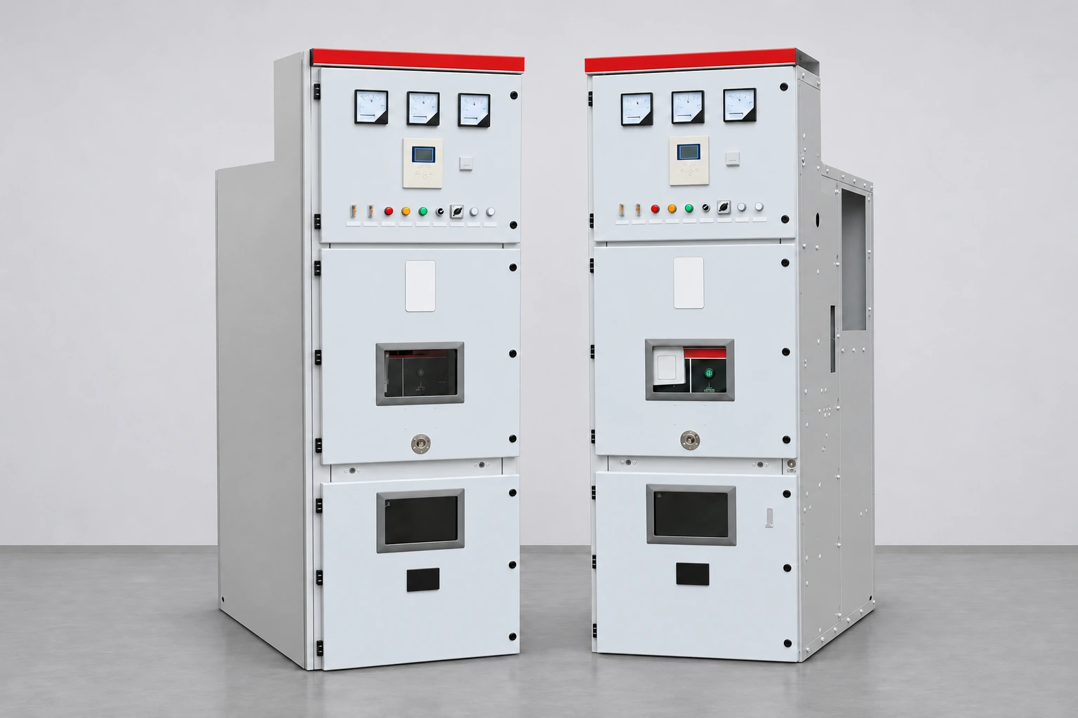
Ask for a controlled schematic, terminal references, relay function identification, relevant settings and an agreed functional test plan. Each required state should have an expected indication and alarm result. The plan should identify which functions are verified at the factory and which depend on final site wiring or control-room integration. A factory record cannot prove an unconnected remote alarm path at the customer’s site.
Functional testing must be designed and carried out by qualified personnel under an approved safe system of work. It can affect the availability of protection and may operate a breaker or produce unexpected indications. The authorized work plan must address isolation, stored energy, verification of safe conditions, protection availability and controlled restoration. Applicable law, site operating rules and equipment instructions govern the work; an alarm checklist cannot replace those requirements.
This article deliberately provides no instructions to bridge terminals, remove supply fuses, disconnect coils or bypass interlocks. The project test plan must establish safe conditions and restoration controls for any authorized test. Reviewers should evaluate the resulting evidence rather than improvising circuit changes to reproduce a demonstration seen elsewhere.
An unhealthy indication should trigger the site’s defined response for potentially impaired tripping capability. It is not automatically a diagnosis of a defective relay. Supply problems, wiring discontinuity, an intentional test isolation or state-related issues may require different investigations. The operator needs the correct equipment identity, current operating state and protection availability information before making an authorized decision.
Do not clear or suppress an alarm simply to obtain a normal display. Record when it appeared, the associated breaker state, other relevant alarms and recent authorized work. Qualified staff should use the approved drawings and procedures to investigate. If the design intentionally inhibits supervision in a particular position, verify that the indication matches that design and does not hide an unrelated problem.
The operating philosophy should state who receives the alarm and who decides any necessary restriction or outage. Whether closing is blocked or other action is required depends on the approved system design. A universal rule to trip immediately on every supervision alarm could create a different operational risk; ignoring every alarm would leave possible impairment unresolved. The documented project response supplies the decision path.
Imagine a hypothetical panel whose supervision alarm appears correctly on the relay display during an authorized factory test. The local test is successful, but the project’s control-room point list uses a different source address. The acceptance record should separate these outcomes: the local function has supporting evidence, while the remote alarm path remains open for correction and site verification.
The supplier and integration team should reconcile the point mapping, identify the corrected document revision, and repeat the affected check at the appropriate stage. They should also verify the return-to-normal indication. A screenshot showing a local alarm does not close the remote issue, and a later normal control-room display does not prove that the intended unhealthy state was ever transmitted.
Use this distinction in the switchgear site acceptance checklist. Retain the test state, expected response, actual response, responsible person, evidence reference and restoration confirmation. This creates a useful record for future maintenance, especially after a relay replacement, control-wiring change or integration update that might alter the monitoring boundary.
This Electrical Passionate educational video discusses pre-close and post-close trip circuit unhealthy indications. It is supplementary circuit explanation, not an approved procedure for work on an operating panel. Use only the actual manufacturer drawings and authorized site procedures for practical work.
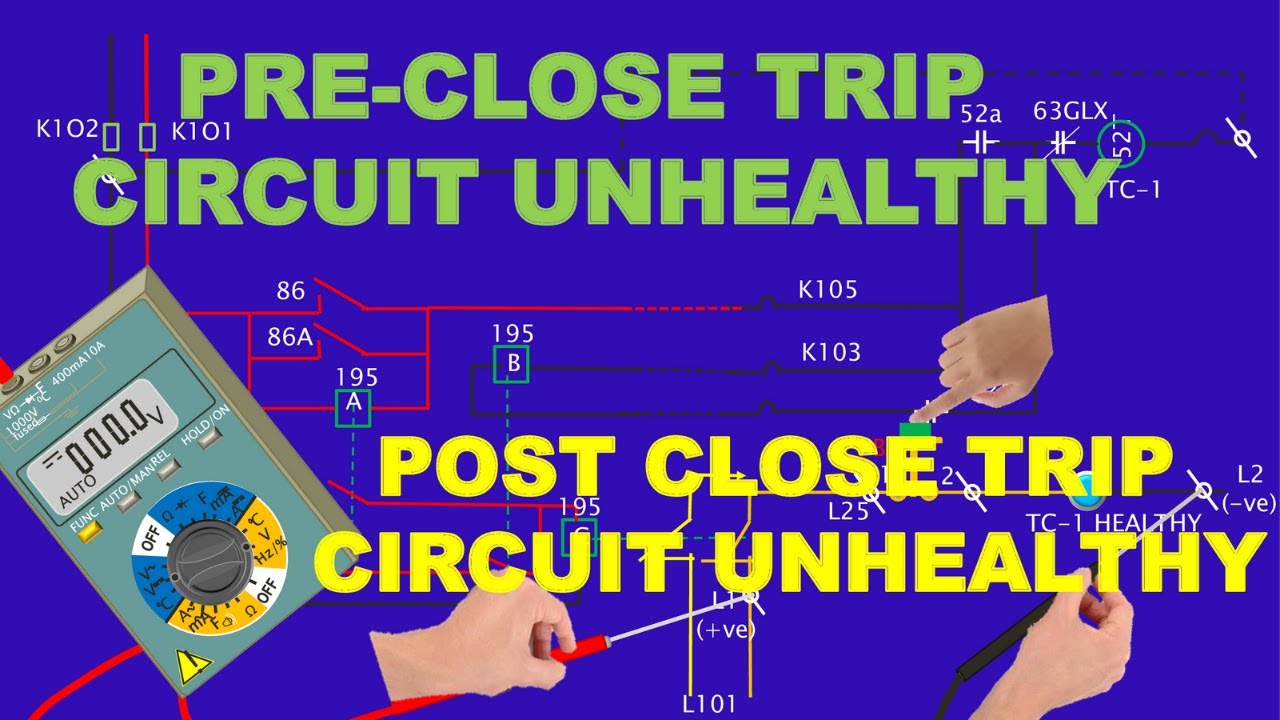
Further learning: TRIP CIRCUIT UNHEALTHY:PRE CLOSE AND POST CLOSE TRIP CIRCUIT UNHEALTHY:WITH EXPLANATION IN DETAILS — Electrical Passionate. Open the video on YouTube.
No. It supports the health of the monitored electrical path under the scheme’s conditions. It does not prove mechanical operation, protection contact operation or every protection function; those require their own applicable checks.
No. Supply supervision can show that control energy is available at a monitored point. Trip circuit supervision may cover additional wiring and the trip coil, depending on the actual design and breaker state.
The approved protection and operating philosophy determines the response. The alarm must receive a defined, timely assessment; a generic article cannot prescribe the correct operating action for every installation.
Only the connected and tested scope can be verified there. Final site wiring and control-room integration may need separate checks, with the outstanding work identified in the acceptance records.