Shenheng Power Equipment Co., Ltd.
- Home
- Products
Products
Since 2001, Shenheng Power has been a trusted manufacturer of power transmission and distribution equipment, delivering reliable electrical solutions globally.

- Solutions
- News & Blog
- Service
- About Us
- Contact Us
Since 2001, Shenheng Power has been a trusted manufacturer of power transmission and distribution equipment, delivering reliable electrical solutions globally.
11kV HT panel protection coordination rests on the project record, not on a cabinet label. Establish the protected system boundary, the latest single-line diagram, the source of approved settings, and the team that will verify commissioning evidence.
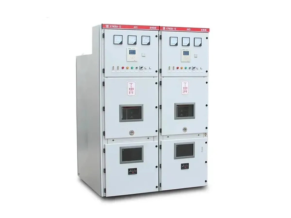
For related panel review steps, see the 11kV breaker specification checklist and KYN28 switchgear interlock verification.
Important: IEC 62271-200 gives metal-enclosed switchgear context; it does not assign relay settings or approve live work for a specific installation. (IEC 62271-200)
Protection coordination is a project activity, not a switchgear label. Begin by identifying the protected circuit, upstream and downstream devices, the controlled drawing revision, the parties responsible for studies and settings, and the conditions that the approved design expects the system to handle.
Use the current single-line diagram to identify sources, transformers, feeders, bus sections, switching devices, instrument transformers, and protective functions included in the project scope. If the diagram, equipment schedule, and panel documentation do not agree, resolve the discrepancy before a setting or test discussion proceeds.
| Coordination input | Current project evidence | Review use |
|---|---|---|
| Network one-line | Controlled system drawing | Establishes device relationships |
| Protection study reference | Approved calculation or instruction | Identifies the source of setting decisions |
| Panel schedule | Equipment role and designation | Connects physical cubicles to project scope |
| Test responsibility | Commissioning plan assignment | Defines who checks each result |
| ## Part 3. Separate panel interfaces from setting decisions |
The panel arrangement may provide the physical location for breakers, instrument transformers, relays, wiring, and interlocks, while the project protection study determines the settings and coordination decisions. Record interfaces that affect the review, but do not infer settings, relay logic, or fault performance from an enclosure image or generic equipment description.
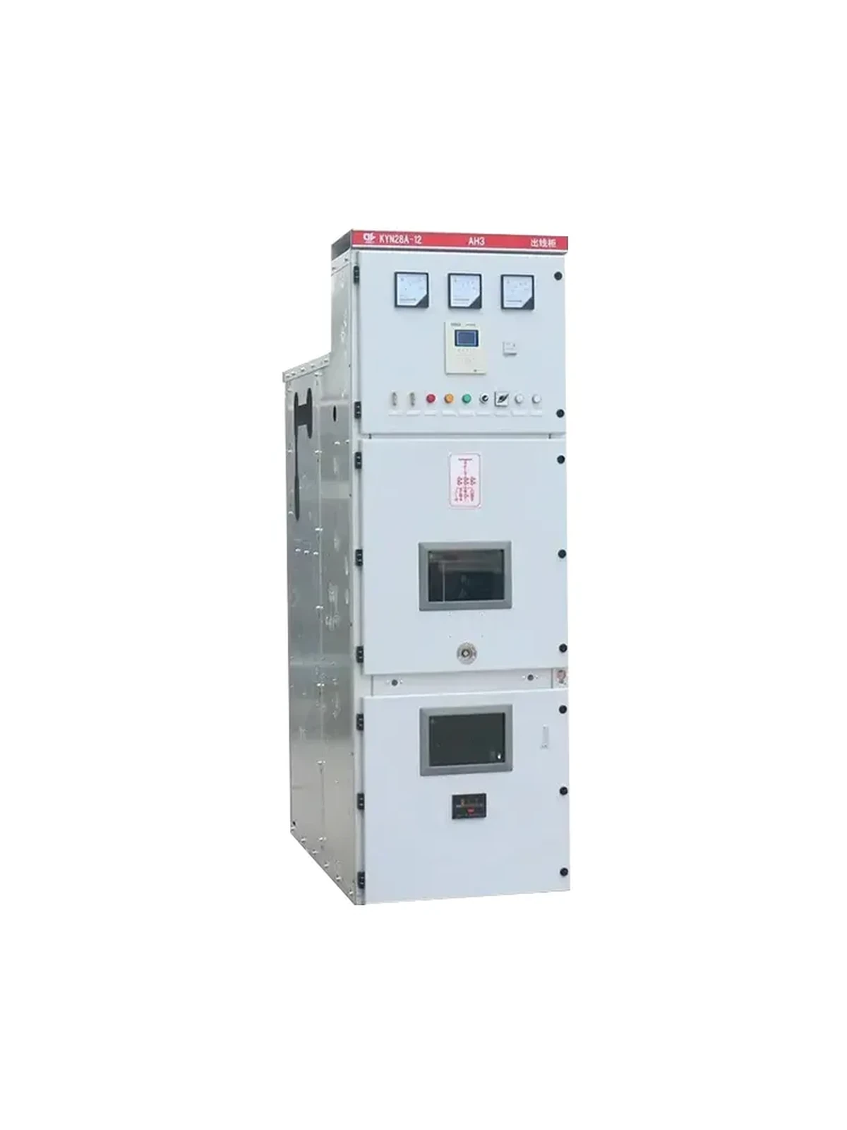
The project should identify who issues the approved setting record, who enters or checks it, who verifies the secondary wiring and functional logic, and who controls revisions after energization. A clear ownership record helps prevent a setting change from being treated as a routine panel adjustment.
Before energization, compare the installed arrangement with the approved drawings, protection setting record, test plan, interlock requirements, cable and secondary wiring records, and open actions. The exact tests and acceptance criteria must come from the approved commissioning plan and qualified personnel.
| RFQ / project input | Record to obtain | Responsible party |
|---|---|---|
| Setting release | Authorized version and date | Protection design owner |
| Secondary-circuit verification | Approved test evidence | Commissioning lead |
| Interlock status | Required functional record | Panel and site team |
| Post-energization change | Change-control reference | Operations authority |
| ## Part 6. Use a product page as a configuration starting point |
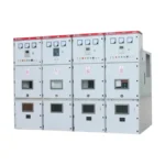
Shenheng Power lists a KYN28-12 medium voltage switchgear system for catalogue discussion. Use it to frame configuration questions once the voltage arrangement, equipment role, interface needs, and project documents are available. It does not prove an installed panel has a particular protection function or approved setting.
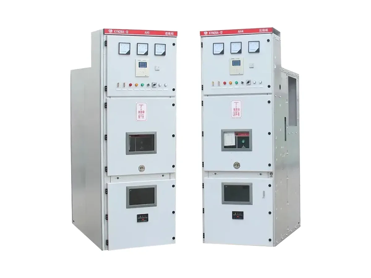
Product recommendation: review the KYN28-12 medium voltage switchgear system only as a catalogue reference for the controlled project review.
The final project record should link the approved drawings, protection study references, setting version, test and commissioning evidence, device identity, change control, and responsibility contacts. This gives operations and maintenance teams a basis for later review without recreating the original design decision.
For an 11kV panel discussion, contact Shenheng Power with the one-line diagram, panel schedule, required interfaces, document list, and requested engineering scope.
It is the controlled review of how protective functions and devices are intended to work across the project system, using the approved design, study inputs, settings record, and commissioning plan.
No. A product page can support a catalogue discussion, but settings and relay logic must come from the approved project protection study and responsible engineering process.
Review the current single-line diagram, equipment information, approved setting record, test plan, secondary wiring and interlock records, change notices, and outstanding actions required by the project.
The project should name the authorized design or protection owner, the person responsible for implementation or checking, and the change-control record. Do not treat settings as unowned panel parameters.
Interlocks and protection functions are related system interfaces, but their exact roles and verification requirements must follow the approved design and commissioning procedure.
Provide the approved or available single-line diagram, voltage arrangement, panel role, equipment schedule, interface needs, requested documents, project environment, and the scope of engineering review required.