Shenheng Power Equipment Co., Ltd.
- Home
- Products
Products
Since 2001, Shenheng Power has been a trusted manufacturer of power transmission and distribution equipment, delivering reliable electrical solutions globally.

- Solutions
- News & Blog
- Service
- About Us
- Contact Us
Since 2001, Shenheng Power has been a trusted manufacturer of power transmission and distribution equipment, delivering reliable electrical solutions globally.
A transformer oil dielectric breakdown test is a controlled field check used to detect reduced dielectric strength caused mainly by water, particles, fibers, or poor sample handling. A useful test is not simply a number on an instrument. It begins with safe isolation, uses a repeatable connection and documented conditions, and ends with comparison against the correct manufacturer limits and the asset’s own history.
This guide explains the practical sequence for the insulating liquid used to separate and cool energized transformer parts. It is written for owners, EPC teams, commissioning engineers, and maintenance planners who need to define scope, review a contractor report, or decide whether an unusual result needs further investigation. It does not replace the equipment manual, an approved switching procedure, or the judgment of a qualified electrical test professional.
The test is designed to detect reduced dielectric strength caused mainly by water, particles, fibers, or poor sample handling. It is strongest when the same method, connections, instrument class, and correction rules are used over time. That produces a baseline that can reveal slow deterioration before it develops into overheating, insulation failure, or an unplanned outage.
It cannot identify every defect by itself. Electrical assets are systems: connections, insulation, mechanisms, cables, controls, environment, and loading interact. A credible diagnosis combines the reading with visual condition, operating history, thermal information, protection records, and complementary electrical or oil tests. A single result copied from a different asset or standard is not a defensible acceptance criterion.
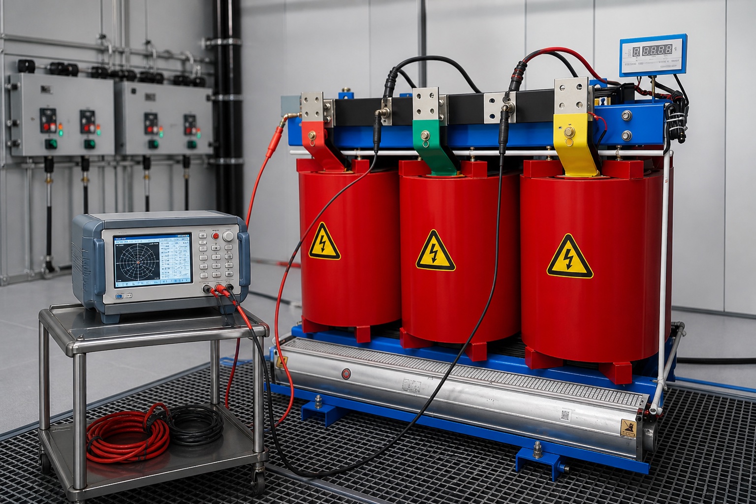
Confirm the oil type and the required test method because electrode shape, gap, stirring, rest time, and voltage ramp affect results. Use a clean, dry sampling container and take the sample from the correct valve after safely flushing stagnant oil.
Define the decision before technicians arrive. Is this an acceptance test, a post-maintenance check, a condition-based survey, or an investigation after a trip? The purpose determines which sections are tested, which auxiliary components are disconnected, how many repeat operations are needed, and what comparison data must be available. Include drawings, nameplate details, serial numbers, tap or breaker position, and the exact test points in the work pack.
The instrument for this work is a clean, calibrated oil breakdown-voltage test set with the specified electrode geometry. Its measurement range, output, accessories, and safety features must fit the asset. Calibration should be current and traceable under the organization’s quality program. Inspect leads and clamps before use; poor contact, damaged insulation, or an unsuitable extension lead can create misleading results and expose personnel to stored energy.
Only qualified people should perform this work. The responsible person must identify every possible electrical source, follow the site lockout and switching process, verify absence of voltage with an appropriately rated device, apply protective grounds as required, and control stored electrical and mechanical energy. Adjacent energized equipment and induced voltage also belong in the risk assessment.
Some tests charge capacitance or magnetize an inductive circuit. The equipment can retain dangerous energy after the instrument is switched off. Use the tester’s discharge indication, wait for the approved discharge period, verify the condition, and reapply grounds before anyone changes connections. Never assume a low test voltage means a low-energy situation.
Use a written data sheet rather than transcribing results later. Record the first reading, stabilized reading, timing, range, applied current or voltage, equipment state, ambient conditions, and any unusual sound or movement. If a value appears abnormal, pause and repeat the connection check before increasing stress or operating the device repeatedly.
A breakdown voltage is method-specific. Interpret it with sample temperature, appearance, moisture data, oil history, and laboratory quality controls rather than comparing one number with a limit from another standard.
| Review point | Reassuring pattern | Reason to investigate |
|---|---|---|
| Breakdown series | Repeatable values with acceptable spread | Low values or excessive scatter |
| Sample appearance | Clear, no visible water or debris | Cloudiness, sediment, or free water |
| Trend | Stable relative to same method | Meaningful decline under comparable conditions |
Start with data quality. Confirm the correct terminals, solid lead contact, stable instrument supply, intended asset position, and adequate settling time. Apply only the temperature or method correction recognized by the governing procedure. Compare equivalent phases or paths, but remember that design asymmetry can be legitimate. Factory data, commissioning data, and a stable field trend are better references than an unexplained percentage found online.
A low or widely scattered series may reflect water, particles, fibers, carbon, bubbles, dirty glassware, a damaged sample valve, or careless transport. When a result is suspect, document the evidence and use the least intrusive next check first. That may mean cleaning and reconnecting leads, repeating at the same conditions, inspecting a joint, checking an auxiliary circuit, or scheduling a complementary diagnostic. Do not repeatedly operate or stress equipment that shows signs of active damage.
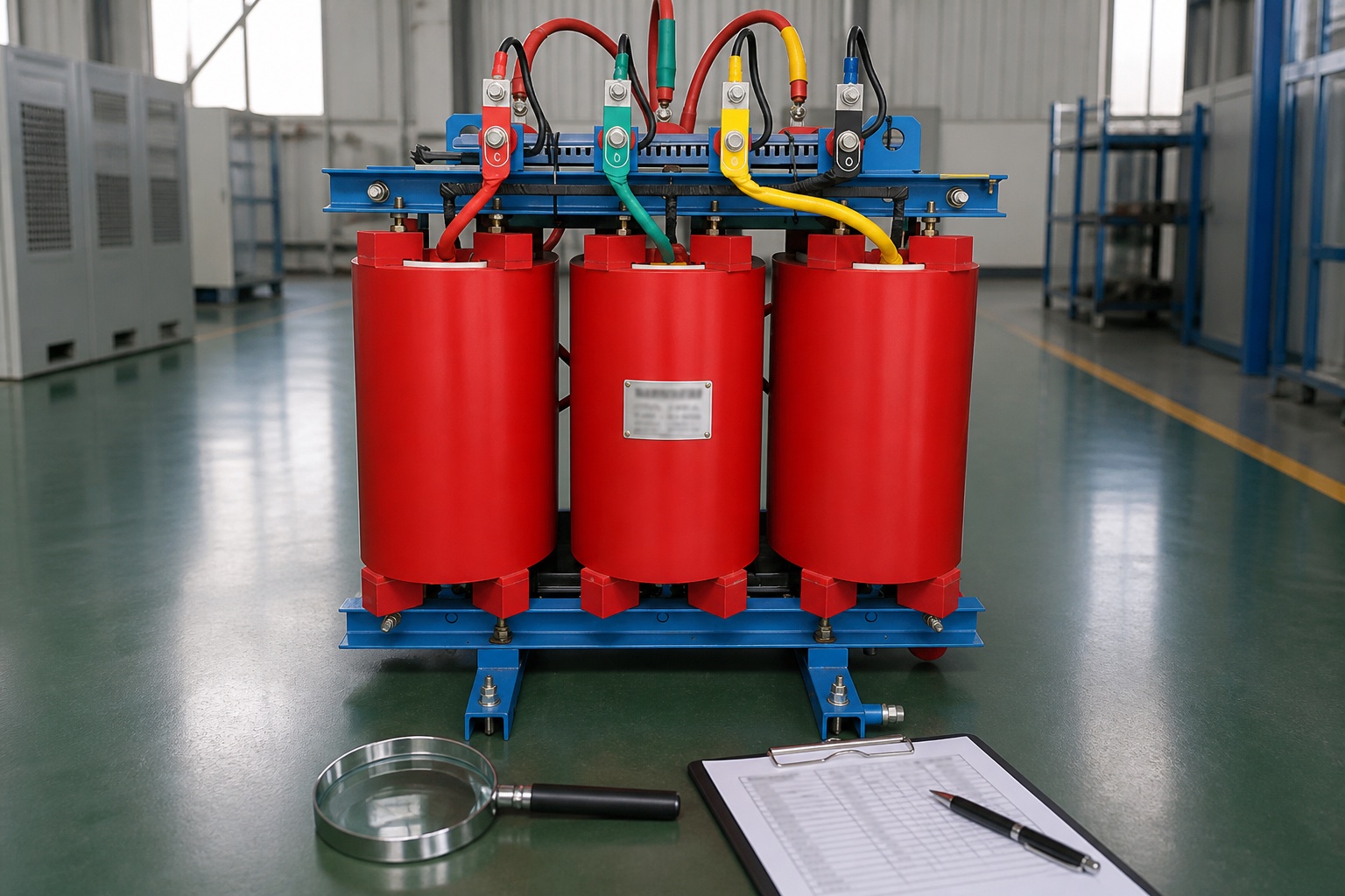
A complete report identifies the project, asset, manufacturer, model, serial number, ratings, location, and tested section. It states the work instruction and reference standard, instrument make and model, calibration due date, connection diagram, equipment position, environmental condition, and safety status. Raw results should be preserved alongside any corrected or calculated result.
The conclusion should separate observation from interpretation. “Phase B measured higher than phases A and C” is an observation; “inspect the Phase B connection because the difference persisted after lead reconnection” is a recommendation. Include photographs and trace files when they help a later reviewer reproduce the decision. Record corrective work and the as-left retest rather than overwriting the as-found value.
Testing creates value when results lead to action. Assign each finding a disposition: acceptable for service, monitor at a defined interval, correct before energization, or remove from service for engineering investigation. Add the result to the asset history and use the same identifiers in work orders, infrared surveys, oil reports, and protection events.
Set the next interval from risk rather than habit. Consider equipment criticality, age, duty, fault exposure, environment, previous defects, spare availability, and the consequence of failure. A stable low-risk asset may justify the normal program interval, while a deteriorating trend or severe operating event may require an earlier targeted check. Document the reason so the next reviewer understands why the interval changed.
For new projects, test access and maintainability should be discussed during procurement. The configuration of the 35kV oil-immersed power transformer affects terminal access, compartment arrangement, environmental protection, and the baseline information supplied at delivery. The broader transformer oil sampling guide helps place this check within a coordinated commissioning or maintenance plan.
Use the edition named in the project specification and the manufacturer’s instructions. These neutral reference pages are useful starting points for safety, maintenance scope, and calibration:
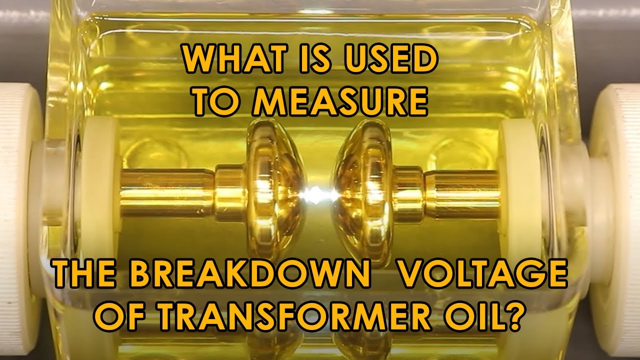
Its main purpose is to detect reduced dielectric strength caused mainly by water, particles, fibers, or poor sample handling. The result should be evaluated with manufacturer guidance, comparable readings, and asset history.
The primary circuit is normally isolated and placed in an electrically safe work condition. Any energized diagnostic work needs a specific approved procedure, qualified personnel, and a risk assessment.
No. Confirm test configuration, lead contact, instrument condition, temperature, humidity, and repeatability first. Escalate a persistent abnormal result for engineering review and complementary tests.
Record asset identity, nameplate data, circuit and test configuration, instrument and calibration status, environmental conditions, raw readings, corrections, acceptance reference, as-found and as-left condition, and recommendations.
A disciplined transformer oil dielectric breakdown test is therefore a decision process, not a checkbox. Safe preparation and repeatable data protect people first; careful interpretation then turns the measurement into a practical reliability action.