Shenheng Power Equipment Co., Ltd.
- Home
- Products
Products
Since 2001, Shenheng Power has been a trusted manufacturer of power transmission and distribution equipment, delivering reliable electrical solutions globally.

- Solutions
- News & Blog
- Service
- About Us
- Contact Us
Since 2001, Shenheng Power has been a trusted manufacturer of power transmission and distribution equipment, delivering reliable electrical solutions globally.
Cable entry and grounding for a substation type transformer should be reviewed as an interface record. It connects the installed transformer, cable schedule, earthing design, enclosure details, inspection evidence, and the engineer responsible for acceptance.
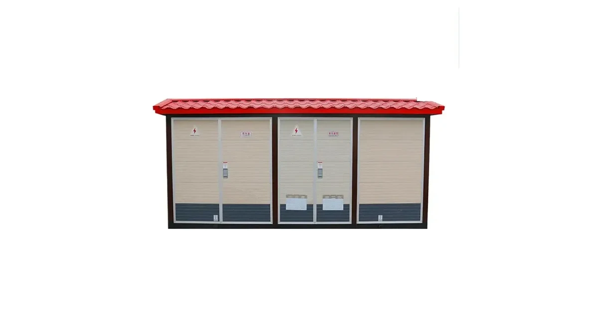
For related context, read the planning delivery for a utility substation transformer and distribution transformer substation EPC planning.
Important: The applicable IEC context is IEEE Std 80: Guide for Safety in AC Substation Grounding. The approved earthing design and qualified engineering team, rather than this note, determine the cable route, bonding method, measurements, safeguards, and acceptance.
A substation type transformer cable-entry and grounding review should start with the approved single-line diagram, equipment layout, cable schedule, earthing design, responsible engineer, and safe-work requirements. A product image cannot set a cable route, conductor size, or acceptance value.
Match the equipment identity, transformer compartment, cable-entry location, gland or termination arrangement, enclosure sections, access panels, and approved changes to the current drawings. Record any mismatch before cable work is accepted.
| Cable-entry baseline | Controlled record | Review purpose |
|---|---|---|
| Transformer compartment identity | Layout and equipment schedule | Confirms the enclosure section |
| Entry and termination route | Cable schedule and detail drawing | Connects cable work to the design |
| Earthing interface | Earthing drawing and bonding record | Identifies the controlled grounding basis |
| Change status | Issued design change record | Prevents an obsolete drawing from governing work |
| ## Part 3. Review cable-entry details against the project record |
Capture entry direction, bend and support context, sealing or mechanical protection requirements, phase identification, termination evidence, and the document owner for each interface. The applicable project specification controls the final detail.
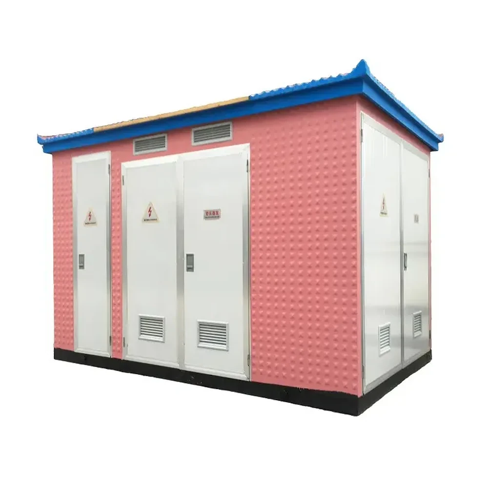
Link the transformer tank or enclosure bonding, main earthing connection, cable-screen or neutral treatment where applicable, continuity evidence, and earthing drawing to the approved design. Do not infer a universal grounding arrangement from a generic substation type.
Use the approved inspection plan to record visible workmanship, labels, clearances, access, cable support, bonding continuity evidence, and outstanding actions. Values and acceptance criteria belong to the authorized procedure and qualified personnel.
| Cable-entry RFQ input | Why it is needed | Responsible source |
|---|---|---|
| Transformer layout basis | Defines the cable interface | Electrical design lead |
| Site and interface context | Identifies installation constraints | Project engineer |
| Evidence and open decision | Defines the technical clarification | Commissioning lead |
| Open switching decision and schedule | Frames ownership and response timing | Project authority |
| ## Part 6. Use the compact substation page as catalogue context |
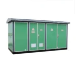
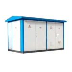
Shenheng Power lists an 11kV/33kV YB series compact outdoor electrical substation for product-family discussion. It does not prove a particular transformer, cable-entry layout, grounding method, rating, or project approval.
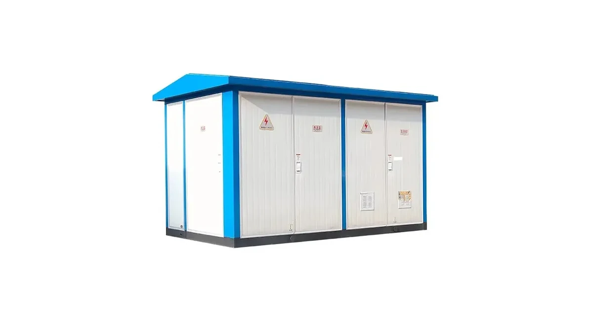
Catalogue fit note: the 11kV/33kV YB series compact outdoor electrical substation is a discussion starting point; confirm cable and grounding interfaces from the approved record.
Retain drawings, cable schedules, earthing records, inspection evidence, deviations, open actions, and approvals. Send the same inputs with an enquiry when the supplier must confirm interfaces or configuration.
For the next engineering step, contact Shenheng Power with the current drawings, equipment role, site or circuit inputs, interfaces, available evidence, document requirements, and questions requiring confirmation for this substation type transformer review.
Include the current layout and single-line diagram, cable schedule, entry direction, termination and sealing context, support, phase identification, earthing design, inspection evidence, and open actions.
No. The approved earthing design, system arrangement, applicable project requirements, and qualified engineering review define the method.
Link the equipment schedule, layout, cable schedule, termination details, issued changes, inspection records, and the owner of each unresolved interface.
Retain the approved earthing drawing, bonding and continuity records, cable-screen or neutral decisions where applicable, inspection evidence, deviations, and approvals.
Keep it open when drawings conflict, an interface is incomplete, evidence is missing, or the responsible authority has not accepted the installation condition.
Provide the equipment role, voltage and circuit arrangement, cable schedule, entry and termination details, site context, earthing requirements, documents, quantity, schedule, and clarification questions.