บริษัท เสินเฮิง พาวเวอร์ อีควิปเมนท์ จำกัด.



Ring main unit cable testing is the controlled verification of a medium-voltage cable circuit connected to, or prepared for connection to, an RMU. The test scope may include conductor continuity, phase identification, insulation or sheath checks and an approved withstand or diagnostic test. The correct method depends on cable type, voltage class, age, accessories and everything connected at the RMU. Testing must be planned with the cable, termination and switchgear manufacturers and performed by qualified personnel on isolated, proved-dead and grounded equipment.
Define the question before selecting a test
A new-cable acceptance test asks whether installation damage or workmanship defects are present before service. A maintenance test asks whether an in-service asset shows deterioration or a significant change. A fault-location activity asks where a known defect lies. These objectives use different equipment and interpretation. “Megger the RMU cable” is not an adequate specification because it omits test voltage, duration, connection, acceptance criteria and treatment of connected equipment.
Identify the cable route, length, conductor size, insulation, screen and sheath construction, joints, terminations and operating voltage. Record the RMU make, model, rated voltage, cable-compartment arrangement, test access and connected devices. For a Shenheng ring main unit, request the project-specific drawing and operating manual rather than assuming all cable test points have identical ratings or interlocks.
Standards and manufacturer limits
IEC 60502-2 covers extruded-insulation power cables and accessories for systems from 6 kV up to 30 kV, while IEC 62271-200 addresses AC metal-enclosed switchgear above 1 kV and up to 52 kV. Their official scopes are available from IEC 60502-2 และ IEC 62271-200. Use the contract editions, local regulations and manufacturer documents for actual values and procedures.
IEEE 400 family guides may also be specified for field testing of shielded power-cable systems. The project must state which method governs. Do not combine a voltage copied from one standard with a duration from another. Accessories, cable age and diagnostic objective matter. A test that is appropriate for new XLPE cable may not be suitable for an aged mixed circuit or for equipment still connected at the far end.
| Test or check | วัตถุประสงค์ | Planning caution |
|---|---|---|
| Continuity and phase identification | Confirm conductor path and phase labels | Prevent false readings through parallel paths |
| Insulation resistance | Basic condition and gross-defect check | Not a complete proof of MV cable condition |
| Sheath integrity | Find damage to oversheath | Isolate bonding and protect accessories as specified |
| VLF AC withstand | Acceptance or maintenance withstand where approved | Voltage, waveform and duration are cable-specific |
| Tan delta or partial discharge | Diagnostic information and trending | Requires suitable equipment and expert interpretation |
| Fault location | Locate a confirmed defect | Energy and method must avoid unnecessary damage |
Isolation and safe preparation
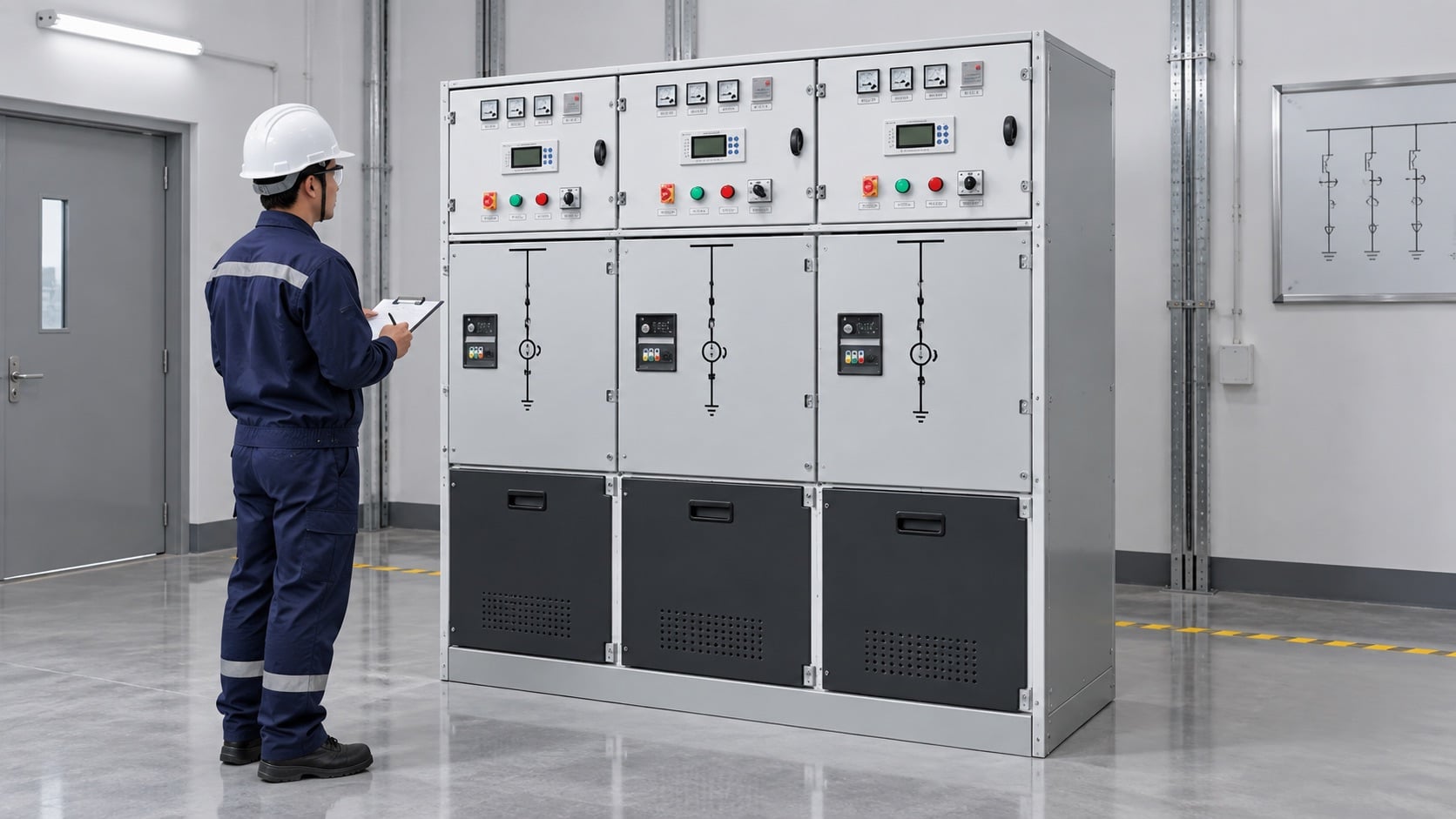
Use the approved switching program to identify all possible sources, including backfeed, embedded generation and induced voltage. Open the correct switching devices, secure them under the site’s lockout system, prove the voltage detector, verify absence of voltage and apply grounding according to the safety rules. RMU mimic diagrams and mechanical indicators help, but they do not replace voltage verification. Treat remote control and stored-energy mechanisms as additional hazards.
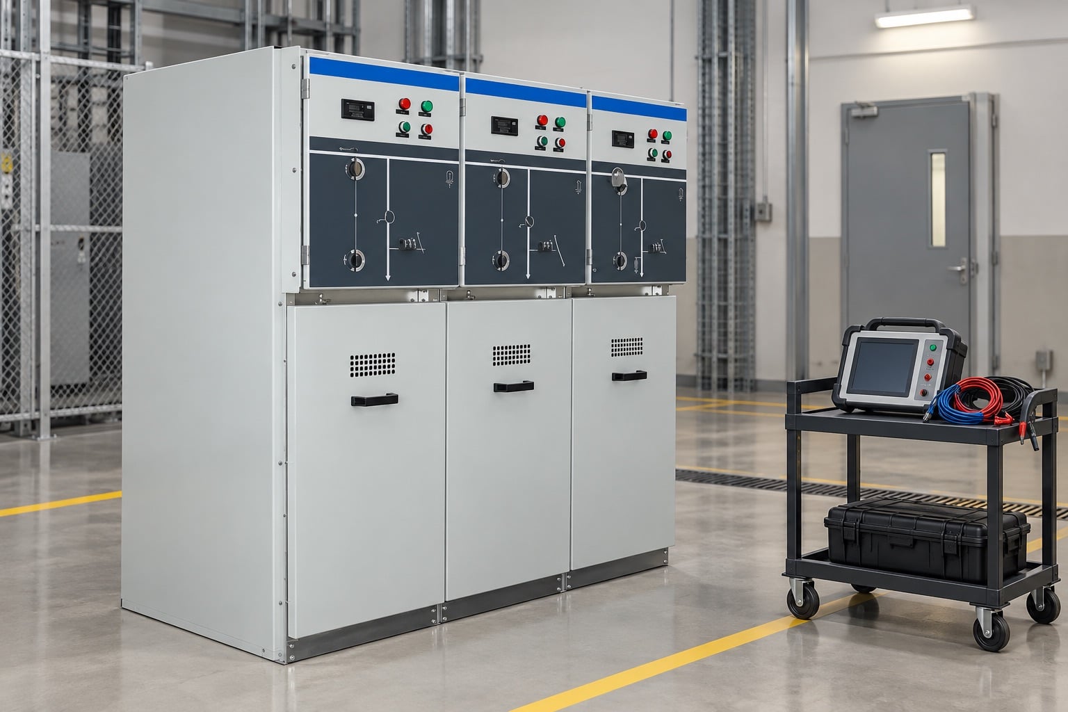
The test boundary should be visible on the one-line diagram. Decide whether the cable remains connected to the RMU test point, is disconnected at the termination, or is isolated by a purpose-designed arrangement. Verify the rating of test plugs and interfaces. Remove or isolate surge arresters, voltage indicators, instrument transformers and sensitive electronics when the approved procedure requires it. At the remote end, prevent access and confirm the same cable identity.
Connection and test sequence
- Hold a pre-test briefing. Review the objective, circuit identity, limits, hazards, communications and stop criteria.
- Inspect the circuit. Check terminations, bonding leads, test points, cable route information and visible damage.
- Verify isolation. Complete lockout, absence-of-voltage verification, grounding and control isolation under the site procedure.
- Configure the boundary. Disconnect or protect equipment not included in the test and secure the remote end.
- Connect with grounds applied. Use rated leads, barriers and discharge devices; then remove only the grounds required by the approved test method.
- Run the specified test. Record waveform, voltage, duration, leakage or diagnostic data and any interruptions.
- Discharge and re-ground. Cables can retain charge; follow the tester and cable procedure before approach.
- Restore the system. Remove test connections, reinstate bonding and accessories, check hardware and complete the switching program.
No single sequence can replace the site procedure. Long cables can store substantial energy, and adjacent energized circuits can induce voltage after a test. Grounding and discharge time must be based on the circuit and equipment, not on an informal waiting period.
Choosing between withstand and diagnostic methods
A withstand test applies a specified electrical stress and produces a pass or breakdown result under defined conditions. A diagnostic test measures properties such as dielectric loss or partial-discharge behavior to support condition assessment. Passing a diagnostic threshold is not automatically equivalent to passing a withstand test, and a single diagnostic value should not be interpreted without cable construction, temperature, length, history and baseline data.
For new extruded cable, VLF AC may be specified where compatible with the cable and accessories. For aged circuits, the owner may prefer a lower-risk diagnostic program or a carefully selected maintenance withstand. DC testing should not be assumed acceptable for every extruded-insulation system. The test provider should cite the governing document, explain the selected stress and confirm compatibility with the RMU interface and connected terminations.
Interpreting results
First check data quality: correct cable length, stable connections, calibrated equipment, environmental conditions and absence of parallel paths. Then apply the acceptance criteria defined before testing. Leakage current alone can be misleading because circuit capacitance, surface contamination and temperature influence the reading. Partial-discharge location plots require expertise to separate real cable or accessory signals from noise and reflections.
If a test stops or indicates a defect, keep the circuit isolated and grounded. Do not repeatedly reapply voltage merely to obtain a pass. Review the event, inspect terminations and joints, verify test configuration and agree on fault-location or repair actions. After repair, repeat only the approved scope and document the as-left condition. Link results to the specific cable ID so future trending compares the same asset.
RMU-specific mistakes to avoid
- Assuming the earthing switch position alone proves the cable is safe.
- Applying test voltage through a voltage indicator or surge arrester not rated for it.
- Using a test plug that fits mechanically but lacks the required electrical rating.
- Forgetting a remote source, parallel feeder or connected transformer.
- Leaving screen bonds, grounds or disconnected links in the wrong final state.
- Closing a cable compartment before completing a tool and debris check.
- Recording only “pass” without voltage, duration, waveform, circuit ID and instrument details.
Operating configuration also matters. The 3-way versus 4-way RMU guide explains feeder-count differences, while the extensible versus non-extensible RMU guide covers future lineup changes. Use the actual panel schedule to identify the feeder under test.
Test report checklist
A complete report records owner, site, circuit ID, cable endpoints, cable and accessory data, RMU section, test objective, governing document, instrument model and calibration, environmental conditions, isolation boundary, test connections, waveform, voltage, duration, readings, acceptance criteria and result. Include anomalies, interrupted tests and repairs rather than presenting only successful values. Signatures should identify the tester and approving engineer under the quality plan.
Before return to service, use an independent restoration check: correct phase identification, screen bonding, termination hardware, test-point caps, shutters, interlocks, earth-switch position, cable-compartment covers and remote-end status. Confirm protection and control availability. The operations team, not the test instrument, authorizes energization.
Building a repeatable maintenance program
Repeat tests are valuable only when the circuit identity, configuration, method and data quality remain comparable. Create a test register that links each result to the cable route, joints, termination replacements and operating events. Trend diagnostic data with the same units and correction method, and preserve raw files rather than only a summary. Review the program after faults, network changes or manufacturer advisories. Testing frequency should follow asset criticality, condition, environment and owner policy; it should not be increased automatically because one result is difficult to interpret. A sound program combines inspection, operating history and protection records with electrical testing, then uses qualified engineering judgment to decide whether to return, monitor, repair or replace the circuit.
Video: how RMUs fit into the substation
This independent substation overview provides context for switching and protection. It is not a cable-test instruction and does not define test voltage.
คำถามที่มักถูกถาม
Can cable tests be performed through an RMU?
Only where the RMU provides an approved, correctly rated test interface and the manufacturer procedure defines the configuration.
Is insulation resistance enough for MV cable acceptance?
No. It is a useful basic check but does not replace the project-specified withstand or diagnostic test.
Should surge arresters remain connected?
Follow the approved system procedure. Arresters and other devices may need isolation because the cable test voltage can be unsuitable for connected equipment.
What must happen after the test?
Discharge and re-ground the cable, restore all bonds and devices, complete an independent configuration check and retain the full test record.