บริษัท เสินเฮิง พาวเวอร์ อีควิปเมนท์ จำกัด.



A breaker-and-a-half scheme is a high-voltage substation bus arrangement in which two circuits share three circuit breakers. Each circuit is connected between two breakers, so either bus can normally feed it and a single breaker or bus can be taken out of service without automatically removing both circuits. The name describes the average breaker count: three breakers serve two circuits. It is chosen where continuity, switching flexibility and fault isolation justify more equipment, protection and control complexity than a single-bus arrangement.
How the breaker-and-a-half arrangement works
A typical bay has two main buses and three breakers in one string. Circuit A connects between the first and middle breaker; Circuit B connects between the middle and third breaker. The middle breaker is shared. Under normal conditions all three breakers may be closed and both buses energized. Current can reach each circuit through two paths, but the exact current distribution depends on the network configuration and operating state. This is not the same as saying that every circuit has one dedicated breaker plus half of a physical breaker; the “half” is an accounting description of the shared center breaker.
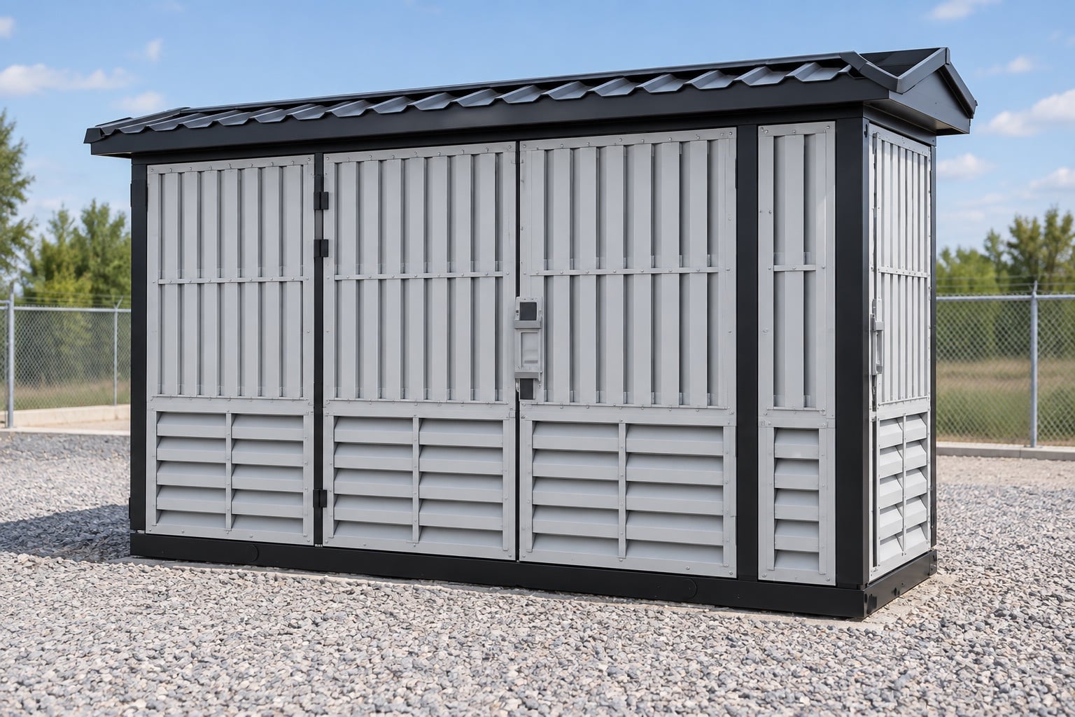
Design drawings must identify buses, disconnectors, current transformers, voltage transformers, grounding switches and line or transformer connections. Equipment numbering and the one-line diagram should make the shared relationship unmistakable. For a packaged project, the high-voltage yard arrangement also needs to coordinate with the transformer, medium-voltage switchgear, station service and protection panels. A compact outdoor substation can serve distribution applications, but it should not be assumed to reproduce an EHV breaker-and-a-half yard; the project voltage, insulation level and duty determine the actual architecture.
Operating states and fault isolation
If one main bus is unavailable, the circuits can generally remain connected through the other bus, provided the remaining equipment ratings and protection logic allow that operating state. If an outer breaker is removed for maintenance, its adjacent circuit can often remain in service through the shared middle breaker. If the middle breaker is removed, both circuits may remain connected through their respective outer breakers, but they no longer have the same redundant path. These are design possibilities, not universal switching instructions. A site-specific sequence, interlocks and control-room authorization are required.
For a line fault, the two breakers bounding that circuit are expected to clear the fault. A bus fault is cleared by breakers associated with that bus zone. Breaker failure protection becomes especially important because a failed shared breaker can affect two circuits. Protection zones, current-transformer placement and trip matrices must be engineered together. The official scopes of IEC 62271-1 และ IEC 62271-100 cover common switchgear requirements and high-voltage AC circuit breakers; the purchased standards, utility criteria and approved study govern the detailed design.
| Arrangement | Approximate breakers per circuit | Continuity | Design burden |
|---|---|---|---|
| Single bus | 1 | Lowest; bus work can affect many circuits | Lowest |
| Double bus, single breaker | 1 | Flexible bus selection, but one breaker per circuit | Moderate |
| Ring bus | 1 | Good continuity; expansion changes the ring | Moderate |
| Breaker-and-a-half | 1.5 | High continuity and maintenance flexibility | สูง |
| Double bus, double breaker | 2 | Very high | Highest equipment count |
Why utilities choose this scheme
The principal benefit is planned-maintenance flexibility. A bus or breaker can often be isolated while circuits remain available through another path. The arrangement also limits the consequence of many single failures compared with simpler schemes. This can be valuable at transmission substations, generating-station switchyards and major interconnection points where an outage has a high system cost. It also gives operators multiple ways to transfer circuits between buses while keeping a clear physical relationship between bays.
The disadvantages are equally real. More breakers mean greater capital cost, larger land requirements, more foundations and structures, more auxiliary power loads and more maintenance. Protection and control require additional current-transformer cores, trip circuits, breaker-failure logic, synchronism checks and status indications. Cable schedules and commissioning tests expand accordingly. Reliability comes from the complete engineered system and disciplined operation, not from the one-line symbol alone.
Protection, control and interlocking questions
Begin with zone boundaries. For each line or transformer, identify the two breakers that must trip for a primary fault. For each bus, identify every breaker in the bus differential zone. Then document what happens if any required breaker fails to interrupt. The shared middle breaker needs carefully coordinated breaker-failure initiation and retripping because it participates in two circuit positions. Duplicate trip coils, DC supplies and communications may be required by the owner’s reliability criteria, but they must not be claimed unless included in the project specification.
Control logic should prevent unsafe disconnector operation and clearly show which devices are energized. Disconnectors are normally intended to provide visible isolation and are not substitutes for circuit breakers interrupting load or fault current. Synchronism and voltage checks may be needed when closing paths that could parallel sources. The operator interface must show abnormal configurations rather than presenting every closed breaker as a normal state. Cybersecurity, event recording, time synchronization and remote-control permissions also belong in the control philosophy.
Ratings and studies that cannot be skipped
Specify maximum system voltage, insulation levels, continuous current, short-circuit breaking current, making current, short-time withstand, operating duty and environmental conditions. Check bus and breaker ratings for credible power-flow states, including maintenance configurations. A remaining bus or shared breaker may carry a different current after an outage. Short-circuit studies must examine contributions from both buses and connected sources; protection studies must confirm sensitivity, selectivity and clearing time for each credible arrangement.
Insulation coordination, grounding, lightning protection, arc-flash assessment and seismic or wind requirements are separate design tasks. The substation single-line diagram guide helps organize primary connections, while the single-bus versus double-bus comparison provides context for simpler alternatives. Neither replaces a project study.
Layout and maintainability review
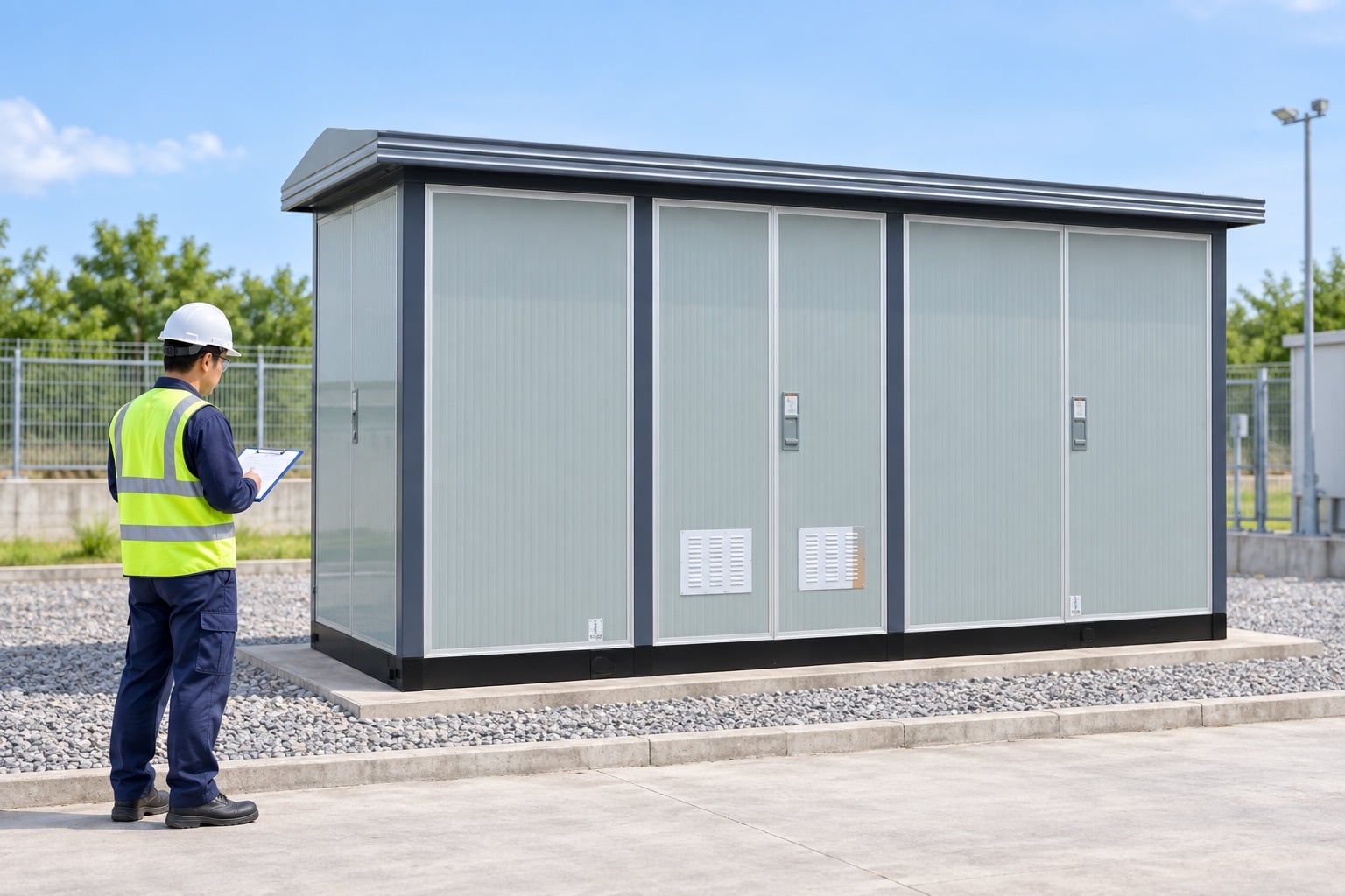
The physical arrangement should allow a breaker, current transformer or disconnector to be isolated, accessed and replaced without exposing workers to adjacent energized parts beyond the approved rules. Review electrical clearances, maintenance envelopes, vehicle access, lifting routes, fire separation, drainage and future expansion. A logical arrangement that looks excellent on paper can be difficult to maintain if equipment removal paths cross live zones or if expansion requires long outages.
Labeling must follow the operating one-line diagram. Bay names, breaker numbers and local control switches should be consistent across drawings, SCADA and field signs. During factory and site acceptance testing, verify point-to-point wiring, interlocks, trip matrices, alarms, breaker-failure initiation, DC supervision and sequence-of-events records. Functional tests should include approved abnormal states, not only the normal all-breakers-closed condition.
Procurement checklist
- Approved one-line diagram showing every breaker, disconnector, CT, VT and grounding point.
- System studies defining continuous current and short-circuit duty for normal and outage configurations.
- Protection philosophy with bus differential, line or transformer protection and breaker-failure trip matrix.
- Control, interlock, synchronism-check, SCADA and DC supply requirements.
- Equipment standards, ratings, type-test evidence and project-specific routine tests.
- Plot plan, clearances, maintenance access, lifting routes and expansion provisions.
- Commissioning plan covering primary injection where required, trip paths and end-to-end protection tests.
Expansion and lifecycle planning
A breaker-and-a-half yard should be planned as a sequence, not only as a final diagram. Define which strings, buses and protection channels are available at each construction stage and how temporary states will be controlled. Space for a future bay is useful only if foundations, bus extension, control panels, DC capacity and communications can be added safely. Lifecycle planning should also account for breaker overhaul intervals, spare mechanisms, replacement lead times and obsolescence of protection relays. An owner comparing schemes should evaluate expected outage cost, maintenance resources and expansion risk over the asset life, not just the initial breaker count. Every later modification requires updated studies, drawings, settings, interlock logic and operator training before the new state is placed in service.
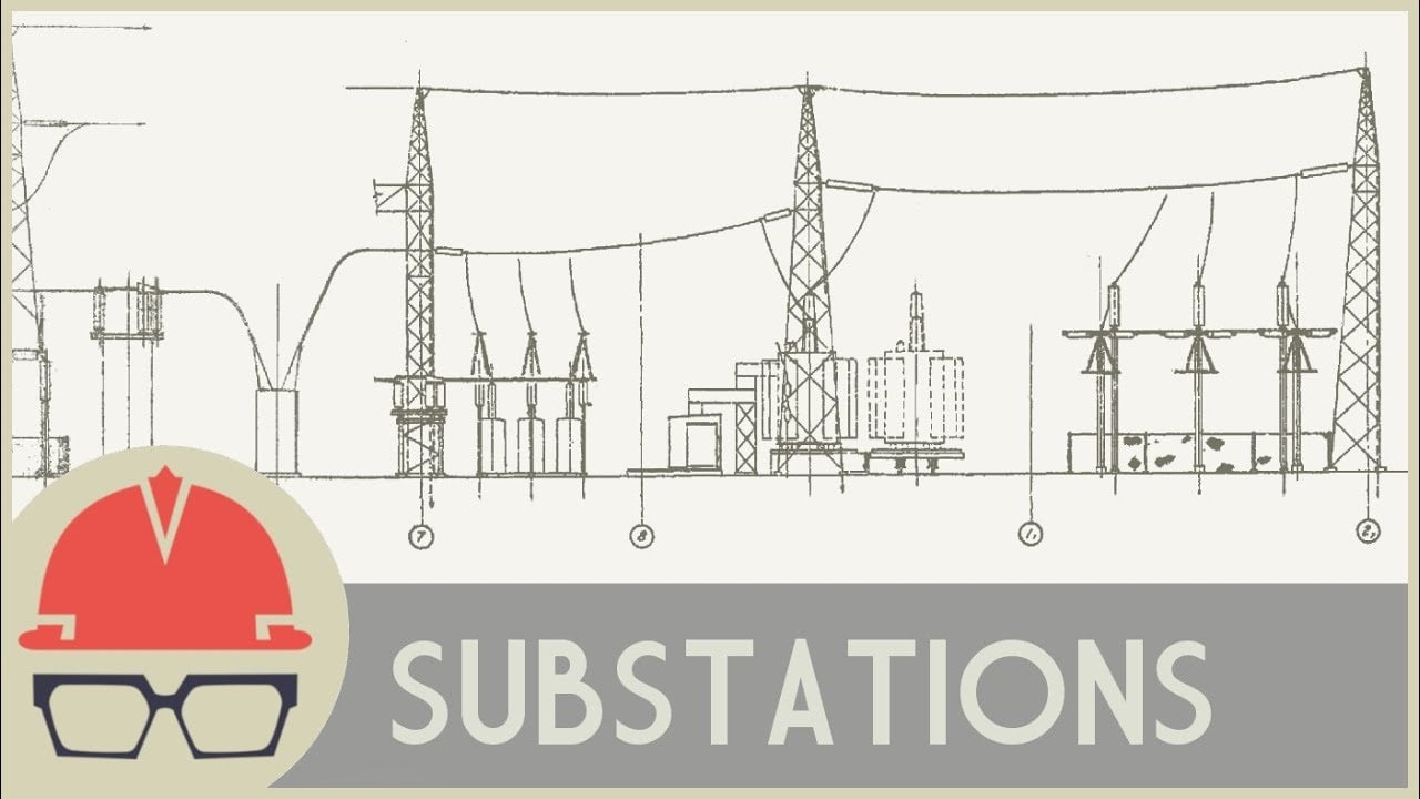
Video: how a substation routes and protects power
This neutral engineering explainer provides useful visual context for buses, breakers and protection. It does not prescribe a project switching sequence.
คำถามที่มักถูกถาม
Why is it called breaker-and-a-half?
Three breakers serve two circuits, which averages 1.5 breakers per circuit. The center breaker is shared by the two adjacent circuits.
Is breaker-and-a-half more reliable than a single bus?
It generally offers greater continuity and maintenance flexibility, but actual reliability depends on protection, control, equipment condition, operating procedures and the wider network.
What happens if the middle breaker is out of service?
Both circuits may remain connected through their outer breakers in a properly designed arrangement, but redundancy and protection behavior change. Operators must use the approved site sequence.
Where is the scheme commonly used?
It is commonly considered for high-voltage transmission substations, generating-station switchyards and major interconnections where outage consequences justify the added equipment and complexity.