Компания Shenheng Power с 2001 года является надежным производителем оборудования для передачи и распределения электроэнергии, поставляя надежные электротехнические решения по всему миру.
Опираясь на комплексную систему послепродажного обслуживания, мы предоставляем экспертные технические консультации, рекомендации по продукции и гибкие услуги OEM и ODM для ваших проектов.
Компания Shenheng Power с 2001 года является надежным производителем оборудования для передачи и распределения электроэнергии, поставляя надежные электротехнические решения по всему миру.
Substation Oil Containment and Transformer Bund Design
Release Time: 2026-10-14
Substation transformer oil containment is a coordinated system that intercepts released insulating liquid, retains it within an approved boundary and prevents contaminated water from escaping through drains, cable trenches or the ground. A concrete bund is one possible component, but its effectiveness depends on available capacity, impermeability, penetrations, rainfall management and inspection. The correct design follows the site’s applicable environmental rules and assessed release scenarios. Do not assume that every transformer needs an identical percentage of oil volume or that gravel alone proves compliance. Buyers should ask for the documented design basis and operating arrangements before accepting the civil layout.
Identify the equipment and the possible release routes
Begin with a complete list of oil-containing equipment within the proposed drainage area. A transformer’s tank is the obvious source, but associated compartments and equipment may need separate consideration. Request the supplier’s confirmed liquid inventory and arrangement. Rated power and a photograph cannot establish oil volume, and a quotation should not infer that value from a similar unit.
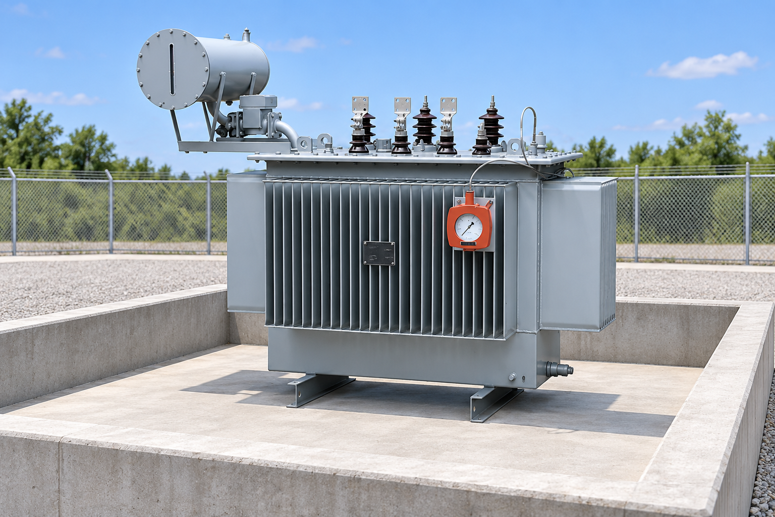
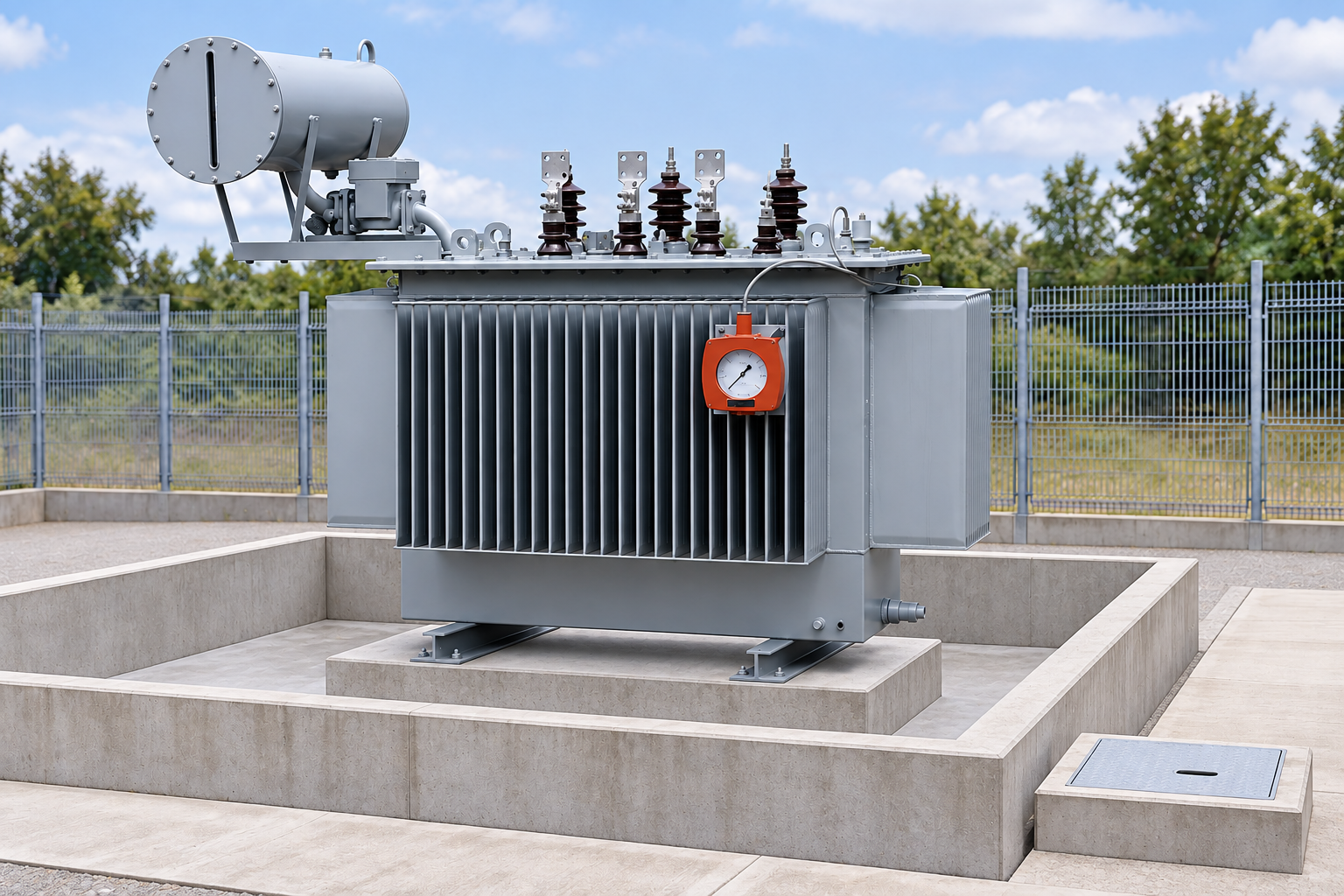
For an oil-immersed industrial transformer, use the approved general arrangement to locate the tank, conservator, filling points, valves and accessible inspection positions. A reference photograph illustrates equipment type; it does not confirm the volume or containment requirement of your ordered transformer. Obtain those facts in the project documents.
Map where liquid could travel following a credible release. Include slopes, cracks, buried services, cable ducts, drainage connections and nearby boundaries. The route can matter as much as the distance to a watercourse. A small opening beneath the equipment can defeat a wide surrounding curb if it leads into an uncontrolled drain.
Separate environmental rules from engineering assumptions
The applicable requirements depend on jurisdiction, facility scope, oil inventory and discharge risk. Do not present one country’s rule as a universal construction specification. For United States projects, qualified reviewers should determine the facility’s applicability under the SPCC framework and identify the relevant provisions. Other jurisdictions and utility owners can use different approval processes and design criteria.
The US EPA guidance for oil-filled operational equipment explains general secondary containment and the need to prevent discharge. It also discusses passive arrangements and active measures in relevant circumstances. That discussion does not mean any gravel bed, spill kit or indoor floor automatically qualifies. The actual arrangement and response capability must meet the requirements applying to the facility.
Record the basis separately for spill prevention, fire protection and electrical safety. These subjects interact, but satisfying one does not establish the others. An environmental engineer, fire specialist, electrical designer and civil designer should agree shared interfaces without using a single generic note to approve the entire station.
Review the containment boundary as a complete path
A bund normally creates a retained area around the equipment. Its walls and floor must work together, and the design should address joints, coatings, penetrations and differential movement. Ask how the chosen materials resist the relevant liquid and environmental exposure. A smooth-looking concrete surface is not independent evidence of liquid-tight construction.
Identify every opening through the boundary. Pipework, cable ducts and foundation interfaces can require approved sealing or isolation details. Show these details on sections and inspect them before they become inaccessible. If a drain is provided, document its control arrangement and who is authorized to release retained water.
Keep access and equipment support separate from the usable retention calculation. The transformer should have a suitable structural support arrangement, while inspection routes must remain workable. A high curb that prevents maintenance access can create pressure for uncontrolled openings later. Resolve that conflict during design instead of leaving it to the operating team.
Assess boundaries, obstructions and penetrations in the volume calculation. Reference-based illustration.
Calculate available capacity using the real arrangement
The capacity assessment begins with the project’s approved release scenario and design allowances. The designer should state which equipment inventories are considered, how rainfall or firewater is addressed and what existing water level is assumed. The resulting required volume belongs to that documented scenario, rather than a universal percentage quoted without context.
Geometric dimensions alone do not establish available capacity. Subtract volume occupied by plinths, equipment supports and other solid obstructions within the retained depth. If granular material is used, only the assessed void space can contribute to storage. Its condition, compaction, blockage and maintenance can change performance, so the design must explain the basis used.
A simple conceptual check is available retained volume minus occupied volume and existing liquid. Every term must use consistent units and the same assumed liquid level. For example, a clean empty rectangular basin’s plan area multiplied by its usable depth gives gross volume, before deducting obstructions or adding project-specific allowances. This relationship is an arithmetic aid; it does not select the release scenario, establish compliance or replace the engineer’s calculation.
Ask for drawings and the calculation to identify the same boundary and levels. If the drawing shows a raised opening below the calculation’s assumed water level, the claimed volume may not be physically retained. Review the lowest uncontrolled escape point rather than measuring only the height of the highest wall.
Design rainfall management without creating a spill outlet
Outdoor containment receives rainfall as well as potential oil. If water accumulates unchecked, it can consume the capacity intended for a release. If water is discharged carelessly, the containment becomes a route for contamination. The operating arrangement must handle both conditions.
For a controlled drain, describe inspection, authorization, release and closure. A valve position alone is not a complete procedure. Personnel need to know how water is assessed, where it may discharge, how the release is recorded and what happens if contamination is suspected. Automatic separation or shutoff equipment requires evidence of suitability, inspection and maintenance under the expected conditions.
Review backflow and flooding from the receiving system. A discharge line can become an inlet during severe weather. The station’s overall drainage layout should show how clean surface runoff stays separate from retained spill areas. Coordinate this with the substation cable trench design; the trench must not provide an unintended escape path or carry oil toward a building.
Keep inspection and controlled drainage responsibilities explicit. Reference-based illustration.
Compare containment options through evidence
The following qualitative table supports a project review. It reflects the prevention and discharge-path principles discussed in EPA’s guidance, rather than prescribing an approved system for every facility. The selected arrangement must be evaluated against local rules and the actual site.
Arrangement
Evidence needed
Failure condition to examine
Impermeable basin or bund
Boundary details, available-volume calculation and inspection method
Cracks, open penetrations, standing water or an uncontrolled drain
Gravel or granular area
Demonstrated retention or discharge prevention basis and maintenance plan
An underlying drain carries oil beyond the controlled area
Remote collection system
Routing, isolation, receiving capacity and access arrangements
Blockage, backflow or connection to an unsuitable outfall
Engineered drainage treatment
Suitability evidence for the liquid and flow conditions, controls and servicing
Bypass, exhausted media, failed sensor or missed maintenance
Active response measures where permitted
Approved response plan, trained people, equipment and deployment timing
Spill reaches the escape path before measures can be deployed
Price comparisons should include construction, commissioning and operating responsibilities. A proposal that excludes drain control or inspection work can appear cheaper while leaving a critical gap. Require tenderers to describe assumptions, limits and excluded equipment explicitly.
Coordinate fire, access and electrical interfaces
Oil retention and fire protection can influence the same layout. Firewater, separation, barriers and emergency access should be assessed by the responsible specialist. Do not infer fire performance from an environmental containment drawing. Likewise, adding a wall should not obstruct required cooling, equipment clearances or safe access.
Ensure grounding and metallic parts are reviewed by the electrical designer. A containment area can contain conductive structures and service routes, and environmental alterations must preserve the approved electrical safety arrangement. Any work around installed equipment requires authorized isolation and site procedures; this article is not a spill-response instruction for live transformers.
Plan transformer replacement. Delivery and lifting routes, removable barriers and temporary spill controls must be defined without defeating the permanent boundary. A future replacement crew should not need to guess which wall section can be removed or where drained liquid should be handled.
Verify the constructed system before handover
Set inspection hold points for the floor, joints, penetrations, drain controls and concealed interfaces. Confirm that materials and construction match the approved details. The responsible engineer should select an appropriate acceptance test; do not improvise filling or discharge tests around electrical equipment.
Compare surveyed levels with the final volume calculation. Confirm that the lowest uncontrolled opening and actual obstructions are represented. Inspect drains for correct destinations and label the controls clearly. Demonstrate alarms or automatic devices using an authorized procedure, and retain the result rather than relying on a supplier brochure.
Используйте transformer oil leak guide for complementary inspection context. Preventing and finding leaks reduces exposure, but it does not eliminate the need for the approved containment arrangement. Both records should be included in the maintenance system.
Keep a practical inspection and response record
An operating check should identify cracks, damaged seals, blocked drains, accumulated water, obstructed access and changes made by later contractors. Assign responsibility for each check and record corrective actions. The frequency should follow the approved plan, equipment instructions and risk assessment rather than an unsupported generic interval.
After a storm or an incident, use the facility’s authorized procedure to assess the system before any discharge. Do not treat clear-looking water as proof that it is suitable for release. Where samples or other checks are required, specify them in the approved plan and preserve the result.
Tie liquid inventory and fluid changes to the asset record. The mineral oil and natural ester comparison explains why liquid selection belongs to a broader equipment assessment. A fluid’s environmental or fire characteristics do not authorize the removal of containment without review.
Further learning: SPCC and inspection responsibilities
The Ohio EPA webinar below includes US EPA presenters and provides educational context for SPCC requirements and inspections. It is a United States regulatory resource, not an approval of a particular transformer installation or a substitute for the facility’s applicable plan.
Further learning: Spill Prevention, Control, and Countermeasure – Oh My! — Ohio EPA. Educational background; this is not an operating authorization. Открыть видео на YouTube.
For additional background, consult the EPA’s SPCC applicability information. Confirm the current official requirements and the responsible professional’s interpretation for your project before procurement or civil approval.
Часто задаваемые вопросы
Does every transformer bund need the same oil-volume percentage?
No universal percentage applies to every jurisdiction and site. The responsible designer must identify applicable rules, release scenarios and allowances, then calculate the available volume of the actual arrangement.
Is gravel alone sufficient oil containment?
Its appearance does not establish containment. The design must demonstrate how the arrangement prevents uncontrolled discharge, including the underlying soil and drainage paths, and how its condition will be maintained.
Can rainwater be released from a transformer containment area?
Only through the facility’s approved inspection and discharge procedure. The arrangement must preserve spill retention and avoid releasing contaminated water or creating an uncontrolled escape route.
What documents should a buyer request before acceptance?
Request confirmed liquid inventory, the design basis, boundary and drainage drawings, capacity calculations, construction inspection results, control tests and an operating maintenance and response plan.
Компания Shenheng Electric Power стремится стать мировым лидером в области решений для энергетического оборудования, помогая клиентам обеспечивать безопасное, эффективное и экологичное управление электроснабжением.

 Шэньхэн Силовое Оборудование Ко., Лтд.