
 Shenheng Power Equipment Co., Ltd.



substation protection zones is a focused engineering question that needs a defined boundary before a calculation, inspection or commissioning decision is made. Substation protection zones divide the primary system into monitored sections so a fault can be detected and the smallest necessary group of breakers can trip. Typical zones include a line, transformer, busbar, feeder, breaker and sometimes a capacitor or reactor. Zones are defined by current-transformer locations and the protection logic, not only by the physical fence or cabinet boundary. Overlap between adjacent zones is deliberate. It prevents a small gap between CTs from becoming an unprotected section, but it must be coordinated so a fault does not cause unnecessary widespread tripping.
Why zones and overlap matter
A protection zone answers two questions: which equipment is protected by a function, and which breakers must open for a fault in that equipment? A line differential zone may end at CTs on both line terminals. A transformer zone normally surrounds the transformer and its bushings. A bus zone includes bus conductors and the relevant breaker connections. The exact boundary follows the approved single-line and protection drawings.
Overlap gives primary protection coverage at boundaries. For example, CTs around a breaker can place the breaker in both adjacent zones. The trip logic must account for faults between CTs and for CT saturation. A protection engineer should document the intended overlap, the backup path and the breaker-failure response. Do not infer the scheme from a single relay nameplate.
CT placement defines coverage
Current transformers are the practical eyes of many protection functions. Their location determines whether a fault is seen by a line, bus or transformer relay and whether the breaker itself sits inside a zone. CT polarity, ratio, class, burden and core assignment must match the study. A drawing that omits CT locations cannot fully explain protection coverage.
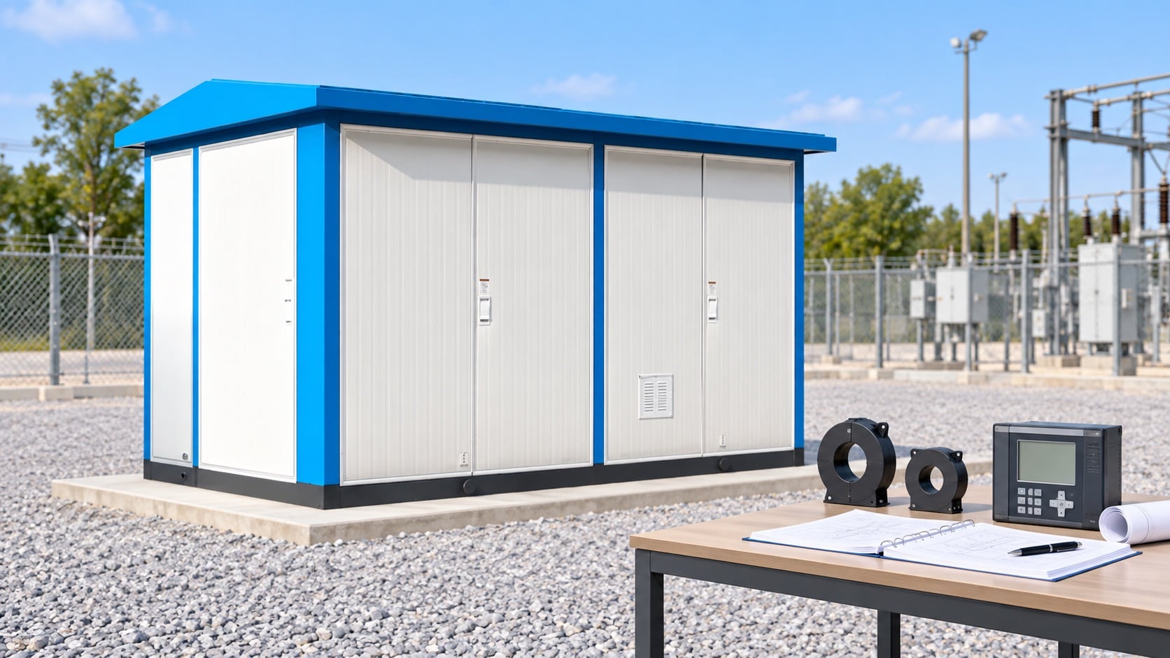
When a compact substation combines transformer and MV switchgear, review the interfaces carefully. Cable terminations, CTs, surge arresters and feeder breakers can be physically close but belong to different electrical zones. Confirm which devices trip for each fault and where test switches interrupt the circuit. Record the final CT wiring and polarity checks in the commissioning package.
Primary and backup protection
Primary protection should clear faults quickly and selectively inside its zone. Backup protection operates when the primary relay, communication channel, breaker or DC supply fails. Backup may trip a larger area and therefore needs time coordination and a clear fault study. Zone diagrams should show both paths.
Do not call a second relay “backup” simply because it has a different model number. Backup needs an independent fault-detection path or a defined failure scenario it can cover. Review duplicated CT cores, separate DC feeds, trip coils, communication channels and breaker-failure timers. The final arrangement depends on utility criteria and the system study.
Busbar and breaker-failure zones
Busbar protection often uses a high-speed differential function. It must distinguish internal bus faults from external faults while tolerating CT errors. Breaker-failure protection starts when a trip is issued but current or breaker status indicates the fault remains. In a breaker-and-a-half or double-bus arrangement, the trip matrix can include several breakers and bus zones.
Test every credible switching state, not only the normal state. A bus coupler or transfer path can change which CTs and breakers belong to a zone. The breaker-and-a-half scheme guide provides context for shared breakers. The bus arrangement comparison explains why topology changes the protection logic.
Transformer zone decisions
Transformer differential protection compares currents on each winding after ratio and phase-shift compensation. Restricted earth-fault protection may cover a narrower winding section. Buchholz, pressure, temperature and other mechanical or thermal functions provide additional evidence. Zone drawings should distinguish electrical differential coverage from mechanical alarms.
Inrush, overexcitation and CT saturation require restraint or blocking logic selected by the study. A protection zone does not authorize arbitrary settings. Use the transformer manufacturer data, system fault levels and relay application guide. If the transformer is inside a compact enclosure, ensure the final cable, switchgear and transformer interfaces match the protection drawing.
Communication and time coordination
Modern substations may use fiber, pilot wire or process-bus signals for differential and interlocking functions. Communication loss must create a known, safe fallback state and alarm. Time synchronization supports event records and sequence analysis. Check that relay clocks, SCADA timestamps and breaker auxiliary contacts agree.
Protection coordination is more than a setting table. Review CT saturation, breaker opening time, DC interruption, arc energy and the network contribution from each source. Keep the study revision, setting file, logic diagram and test report together. When the network changes, recalculate the affected zones instead of copying an old setting group.
Commissioning tests
Commissioning should include point-to-point wiring, CT polarity and ratio, insulation checks where specified, relay logic, trip paths, interlocks, breaker-failure initiation and end-to-end communication tests. Simulate internal and external faults with the approved test set. Record the expected and observed breaker operations.
Test both normal and maintenance configurations. Confirm that a CT shorting link, test switch or local/remote selector cannot silently disable the intended zone. Any temporary test lead must be removed and independently checked. Protect the approved settings from unauthorized changes after handover and keep a controlled backup.
Design and procurement checklist
Ask for the single-line diagram, zone drawing, CT schedule, relay one-lines, trip matrix, breaker-failure logic, DC schematic, communications architecture, setting philosophy and study assumptions. Name the required fault-clearing performance and the credible operating states.
For a compact outdoor substation, request the enclosure and cable layout as well as the protection documents. The product page linked above is a real equipment reference; it does not replace project-specific relay engineering. Keep a protection-zone review as a hold point before energization and after any equipment or topology change.
| Sprawdź | Dowód do nagrania | Dlaczego to ważne |
|---|---|---|
| Definicja | Formuła, stany graniczne i stan działania | Zapobiega porównywaniu przez dwie drużyny różnych ilości. |
| Wyposażenie | Ocenzurowany napięcie, prąd, konstrukcja i zatwierdzony rysunek | Łączy obliczenie lub listę kontrolną z rzeczywistym produktem. |
| Warunki | Środowisko, temperatura, współczynnik mocy lub zanieczyszczenie, w zależności od przypadku | Wyjaśnia, dlaczego zachowanie pól może różnić się od wartości z katalogu. |
| Weryfikacja | Metoda testowania, przyrząd, wynik i podstawy akceptacji | Tworzy sprawdzalny zapis uruchomienia. |
| Kontrola zmian | Odchylenie, zatwierdzenie przez właściciela oraz korekta w stosunku do stanu faktycznego | Zapobiega sytuacji, w której nieprzeczytana zmiana witryny staje się ukrytym ryzykiem. |
Linki do produktów i poradników technicznych
Więcej informacji na temat dopasowania produktu Shenheng można znaleźć w dotycząca strony produktu. W sprawie szerszej tematyki, przeczytaj instrukcja rodzicielska. Literatura do zapoznania się: Pierwsze powiązane przewodniki i drugi odpowiedni przewodnik.
Źródła i standardy
Źródło władz 1 · Źródło władz 2
Jak wykorzystać wynik w projekcie
Rozpocznij od identyfikacji końcowego wyposażenia i opracowanego projektu. Zwróć uwagę na stan eksploatacji, punkt pomiarowy, warunki środowiskowe oraz decyzję, którą wynik musi potwierdzić. Następnie porównaj dowody z obowiązującymi standardami, instrukcjami producenta oraz planem akceptacji projektu. Jeśli którykolwiek z warunków wstępnych jest niedociągnięciem, zachowaj element włączony w system, zamiast uzupełniać luki generowaniem wartości ogólnej. Ta metoda pozwala kupującemu, inżynierowi odpowiedzialnemu za uruchomienie i zespołowi ds. operacji omówić ten sam zasób fizyczny.
W przypadku zapytania od dostawcy należy poprosić o podanie podstawy obliczeń, sprawdzonego układu, ograniczeń, dokumentacji badań oraz odchyleń. W przypadku prac na placu budowy należy zanotować osobę, urządzenie, datę, granicę izolacji oraz kontrolę przywracania stanu pierwotnego. Krótki, ale pełny zapis jest bardziej przydatny niż długi raport, który ukrywa fakt niezbędny do zatwierdzenia kolejnego etapu.
Bezpieczeństwo i kontrola zmian
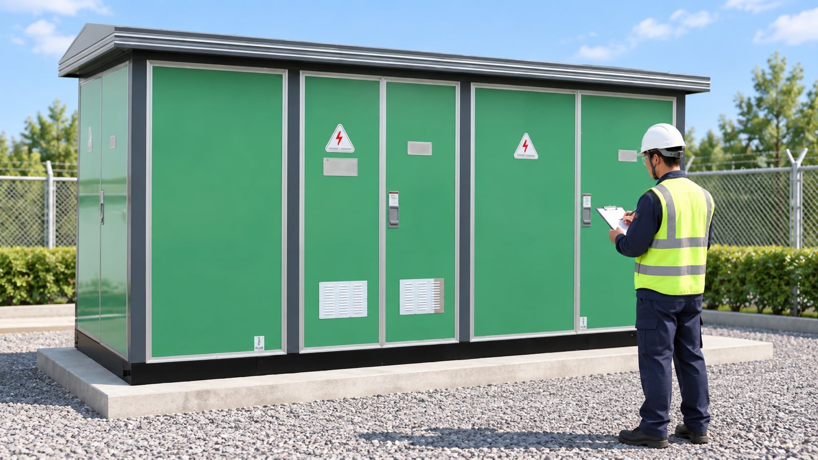
Urządzenia elektryczne mogą przechowywać energię lub pobierać energię z więcej niż jednego źródła. Prace narażające przewody elektryczne, usuwające bariery lub zmieniające funkcję zabezpieczeń lub sterowania wymagają zatwierdzonego pozwolenia, izolacji, weryfikacji braku napięcia oraz kwalifikowanego nadzoru. Ten artykuł nie powinien być używany jako instrukcja dotycząca przesyłania energii. Jeśli zainstalowana instalacja różni się od rysunku, należy zatrzymać się i uzyskać zezwolenie techniczne przed kontynuowaniem prac.
Po wykonaniu testu lub przeglądzie należy przywrócić pokrywy, osłony, zawiasy, zabezpieczenia, etykiety i ustawienia. Wykonaj niezależną kontrolę najważniejszych etapów napraw. Zapisuj wyjątki i powiązaj je z końcowym rekordem aktywów. Dzięki temu zespoły konserwacyjne w przyszłości nie będą polegać na tymczasowym stanie testowym.
Kiedy dowody są niekompletne, należy zidentyfikować brakujące dane i przypisać je do właściciela przeglądu. Nie należy powtarzać wartości oceny, wartości punktu wyjściowego, wartości dopuszczalnej lub wyniku testu z innej rodziny produktów. Wartość rodziny produktów, klasę napięcia i środowisko lokalne należy utrzymywać w stałym zakresie od pierwszego obliczenia do zakończenia procesu przekazania. Dzięki temu późniejsze porównania trendów stają się sensowne i pozwalają dostawcy na przedstawienie jasnego zestawu pytań.
Wideo dla kontekstu systemowego
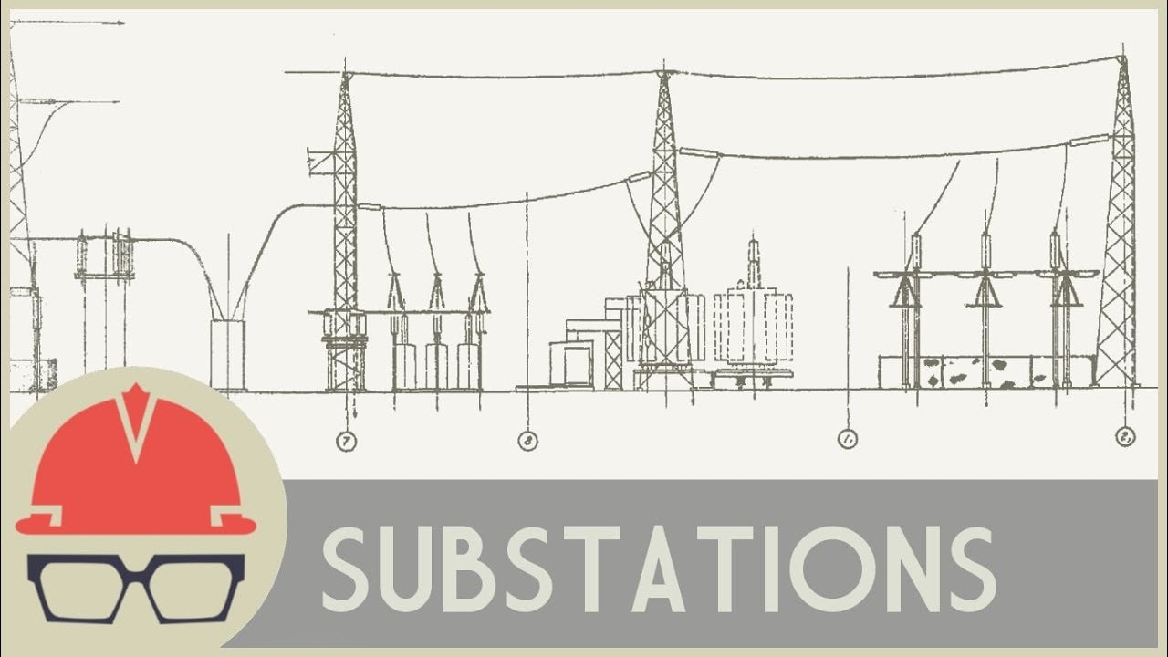
To neutralne wyjaśnienie z serii Practical Engineering dostarcza przydatnych informacji na temat stacji przesyłowych, transformatorów i rozdzielni. Jest to materiał edukacyjny, a nie instrukcja do realizacji konkretnego projektu.
Często zadawane pytania
Jakie jest główne niepowodzenie, którego należy unikać?
Treating one percentage, dimension or indicator as a universal acceptance value. The substation protection zones decision must use the applicable standard, actual equipment and documented conditions.
Czy strona produktu może zastąpić inżynierię projektową?
Nie. Linkowana strona produktu wskazuje na odpowiednią kategorię produktów Shenheng. Oceny, akcesoria, ustawienia i wartości akceptacyjne muszą pochodzić z dokumentów projektu oraz dostarczonego sprzętu.
Czego należy trzymać do przekazania?
Zachować zatwierdzony rysunek, dane z prób, metodę testowania, informacje o instrumentach, odchylenia, końcowe ustawienia oraz dokumentację stanu gotowego urządzenia, aby można było odtworzyć wynik.
Czy to wytyczne zezwalają na pracę na żywo?
Nie. Wykwalifikowany personel musi przestrzegać programu bezpieczeństwa elektrycznego na placu budowy, a także instrukcji producenta.




