
 申恒電力設備有限公司.



substation protection zones is a focused engineering question that needs a defined boundary before a calculation, inspection or commissioning decision is made. Substation protection zones divide the primary system into monitored sections so a fault can be detected and the smallest necessary group of breakers can trip. Typical zones include a line, transformer, busbar, feeder, breaker and sometimes a capacitor or reactor. Zones are defined by current-transformer locations and the protection logic, not only by the physical fence or cabinet boundary. Overlap between adjacent zones is deliberate. It prevents a small gap between CTs from becoming an unprotected section, but it must be coordinated so a fault does not cause unnecessary widespread tripping.
Why zones and overlap matter
A protection zone answers two questions: which equipment is protected by a function, and which breakers must open for a fault in that equipment? A line differential zone may end at CTs on both line terminals. A transformer zone normally surrounds the transformer and its bushings. A bus zone includes bus conductors and the relevant breaker connections. The exact boundary follows the approved single-line and protection drawings.
Overlap gives primary protection coverage at boundaries. For example, CTs around a breaker can place the breaker in both adjacent zones. The trip logic must account for faults between CTs and for CT saturation. A protection engineer should document the intended overlap, the backup path and the breaker-failure response. Do not infer the scheme from a single relay nameplate.
CT placement defines coverage
Current transformers are the practical eyes of many protection functions. Their location determines whether a fault is seen by a line, bus or transformer relay and whether the breaker itself sits inside a zone. CT polarity, ratio, class, burden and core assignment must match the study. A drawing that omits CT locations cannot fully explain protection coverage.
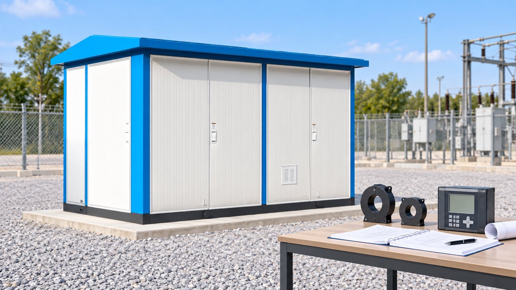
When a compact substation combines transformer and MV switchgear, review the interfaces carefully. Cable terminations, CTs, surge arresters and feeder breakers can be physically close but belong to different electrical zones. Confirm which devices trip for each fault and where test switches interrupt the circuit. Record the final CT wiring and polarity checks in the commissioning package.
Primary and backup protection
Primary protection should clear faults quickly and selectively inside its zone. Backup protection operates when the primary relay, communication channel, breaker or DC supply fails. Backup may trip a larger area and therefore needs time coordination and a clear fault study. Zone diagrams should show both paths.
Do not call a second relay “backup” simply because it has a different model number. Backup needs an independent fault-detection path or a defined failure scenario it can cover. Review duplicated CT cores, separate DC feeds, trip coils, communication channels and breaker-failure timers. The final arrangement depends on utility criteria and the system study.
Busbar and breaker-failure zones
Busbar protection often uses a high-speed differential function. It must distinguish internal bus faults from external faults while tolerating CT errors. Breaker-failure protection starts when a trip is issued but current or breaker status indicates the fault remains. In a breaker-and-a-half or double-bus arrangement, the trip matrix can include several breakers and bus zones.
Test every credible switching state, not only the normal state. A bus coupler or transfer path can change which CTs and breakers belong to a zone. The breaker-and-a-half scheme guide provides context for shared breakers. The bus arrangement comparison explains why topology changes the protection logic.
Transformer zone decisions
Transformer differential protection compares currents on each winding after ratio and phase-shift compensation. Restricted earth-fault protection may cover a narrower winding section. Buchholz, pressure, temperature and other mechanical or thermal functions provide additional evidence. Zone drawings should distinguish electrical differential coverage from mechanical alarms.
Inrush, overexcitation and CT saturation require restraint or blocking logic selected by the study. A protection zone does not authorize arbitrary settings. Use the transformer manufacturer data, system fault levels and relay application guide. If the transformer is inside a compact enclosure, ensure the final cable, switchgear and transformer interfaces match the protection drawing.
Communication and time coordination
Modern substations may use fiber, pilot wire or process-bus signals for differential and interlocking functions. Communication loss must create a known, safe fallback state and alarm. Time synchronization supports event records and sequence analysis. Check that relay clocks, SCADA timestamps and breaker auxiliary contacts agree.
Protection coordination is more than a setting table. Review CT saturation, breaker opening time, DC interruption, arc energy and the network contribution from each source. Keep the study revision, setting file, logic diagram and test report together. When the network changes, recalculate the affected zones instead of copying an old setting group.
Commissioning tests
Commissioning should include point-to-point wiring, CT polarity and ratio, insulation checks where specified, relay logic, trip paths, interlocks, breaker-failure initiation and end-to-end communication tests. Simulate internal and external faults with the approved test set. Record the expected and observed breaker operations.
Test both normal and maintenance configurations. Confirm that a CT shorting link, test switch or local/remote selector cannot silently disable the intended zone. Any temporary test lead must be removed and independently checked. Protect the approved settings from unauthorized changes after handover and keep a controlled backup.
Design and procurement checklist
Ask for the single-line diagram, zone drawing, CT schedule, relay one-lines, trip matrix, breaker-failure logic, DC schematic, communications architecture, setting philosophy and study assumptions. Name the required fault-clearing performance and the credible operating states.
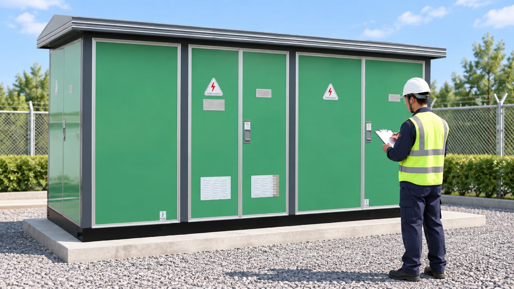
For a compact outdoor substation, request the enclosure and cable layout as well as the protection documents. The product page linked above is a real equipment reference; it does not replace project-specific relay engineering. Keep a protection-zone review as a hold point before energization and after any equipment or topology change.
| 確認 | 記録する証拠 | なぜそれが重要なのか |
|---|---|---|
| 定義 | Formula, boundary and operating state | Prevents two teams comparing different quantities. |
| Equipment | Rated voltage, current, construction and approved drawing | Links the calculation or checklist to the actual product. |
| Conditions | Ambient, temperature, power factor or pollution as applicable | Explains why field behavior can differ from a catalog value. |
| 確認 | Test method, instrument, result and acceptance basis | Creates an auditable commissioning record. |
| 変更管理 | Deviation, owner approval and as-built revision | Stops an unreviewed site change becoming a hidden risk. |
関連製品およびエンジニアリングガイド
Shenheng製品の組み合わせに関する詳細は、こちらをご覧ください。 該当する製品ページ. より広範なトピックについては、こちらをお読みください。 親エンジニアリングガイド. 関連する記事: 最初の関連ガイド そして 2つ目の関連ガイド.
情報源と基準
プロジェクトでその結果をどのように利用するか
Start with the final equipment identity and the released design. Note the operating state, measurement point, environmental conditions and the decision the result must support. Then compare the evidence with the applicable standard, manufacturer instruction and project acceptance plan. If any prerequisite is missing, keep the item open rather than filling the gap with a generic value. This approach helps a buyer, commissioning engineer and operations team discuss the same physical asset.
For a supplier inquiry, ask for the calculation basis, verified arrangement, limits, test records and deviations. For site work, record the person, instrument, date, isolation boundary and restoration check. A concise but complete record is more useful than a long report that hides the one fact needed to approve the next step.
Safety and change control
Electrical equipment can retain energy or become energized from more than one source. Work that exposes conductors, removes barriers or changes a protection or control function requires an approved permit, isolation, absence-of-voltage verification and qualified supervision. Do not use this article as a switching instruction. If the installed arrangement differs from the drawing, stop and obtain engineering disposition before continuing.
After a test or inspection, restore covers, bonds, shutters, interlocks, labels and settings. Use an independent check for critical restoration steps. Record exceptions and link them to the final asset record. This protects future maintenance teams from relying on a temporary test state.
When evidence is incomplete, identify the missing input and assign a review owner. Do not backfill a rating, setpoint, clearance or test result from a different product family. Keep the product family, voltage class and site environment consistent from the first calculation to final handover. This makes later trend comparisons meaningful and gives procurement a clear list of questions for the supplier.
システムコンテキスト用の動画
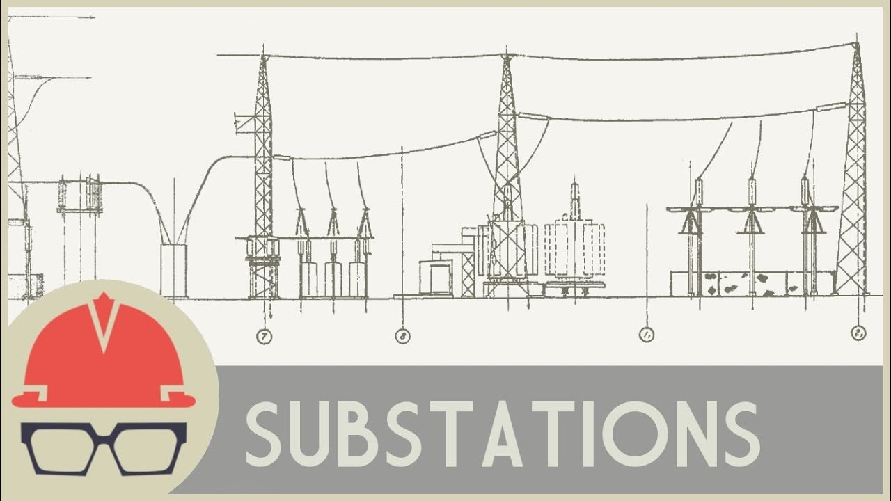
This neutral Practical Engineering explainer gives useful context for substations, transformers and switchgear. It is background education, not a project test instruction.
よくある質問
What is the main mistake to avoid?
Treating one percentage, dimension or indicator as a universal acceptance value. The substation protection zones decision must use the applicable standard, actual equipment and documented conditions.
Can the product page replace project engineering?
No. The linked product page identifies a relevant Shenheng product category. Ratings, accessories, settings and acceptance values must come from the project documents and supplied equipment.
What should be kept for handover?
Retain the approved drawing, raw readings, test method, instrument information, deviations, final settings and the as-built record so the result can be reproduced.
Does this guide authorize live work?
いいえ。資格を有する職員は、現場の電気安全プログラム、絶縁手順、および製造元の指示に従う必要があります。.




