Shenheng Power Equipment Co., Ltd.



Dry type transformer cable termination is the engineered connection between a power cable and the transformer’s primary or secondary terminal. A reliable termination depends on matching voltage class, insulation system, conductor material and size, lug or connector, clearances, enclosure, mechanical support and the transformer manufacturer’s instructions. The work must be performed de-energized by qualified personnel under an approved safety program. This guide explains what to specify, inspect and test; it is not a live-work or field installation procedure.
Start with the transformer and cable data
Record transformer rating, winding voltages, vector group, frequency, terminal arrangement, insulation level and available enclosure space. Then record cable voltage rating, conductor material, cross-sectional area, number of runs per phase, insulation type, screen construction, overall diameter, bending radius and fire-performance requirements. A termination selected from conductor size alone can be electrically or mechanically unsuitable.
Confirm whether the connection is a bolted lug on an exposed terminal pad, an enclosed cable box, a separable connector or a screened plug-in interface. These are different systems. A 6 kV/10 kV cast-resin dry type transformer should be ordered with the terminal arrangement and enclosure that match the project cable design. Do not drill, bend or modify busbars in the field without written manufacturer approval.
Voltage class, insulation and clearances
The termination kit and cable must be rated for the system’s maximum voltage and insulation coordination. For screened medium-voltage cable, stress control at the screen cutback is critical; uncontrolled electric-field concentration can lead to partial discharge and insulation failure. The cable manufacturer’s preparation dimensions and the termination supplier’s instructions are part of the approved design. Air clearances and creepage distances around transformer terminals must remain within the equipment design after all phases and parallel cables are installed.
IEC 60076-11 covers dry-type power transformers, while the IEC 60502 series addresses extruded-insulation power cables and accessories for relevant voltage ranges. See the official scopes for IEC 60076-11 dan IEC 60502-2. Use the editions and local rules stated in the contract; a webpage summary cannot supply project acceptance values.
| Item | Verify | Common consequence if missed |
|---|---|---|
| Cable and kit | Voltage rating, insulation, screen, diameter range | Poor stress control or sealing |
| Conductor interface | Material, area, lug palm and hole pattern | Heating or mechanical mismatch |
| Transformer terminal | Pad size, phase spacing and permitted loading | Damaged terminal or inadequate clearance |
| Cable route | Bending radius, supports and phase sequence | Mechanical strain and installation error |
| Enclosure | IP requirement, gland plate and ventilation | Moisture ingress or restricted cooling |
| Tests | Approved method, limits and records | Damage from an unsuitable test |
Lugs, bolted joints and conductor materials
Select a lug or mechanical connector approved for the conductor material and size. Copper and aluminum require compatible interfaces, surface preparation and joint compounds where specified. The lug palm should sit flat on the terminal pad without being forced into alignment. Use the fastener grade, washers and tightening method stated by the equipment manufacturer. A generic torque chart is not a substitute for the approved joint design.
Parallel conductors need symmetrical routing and equivalent connection conditions so current shares reasonably. Do not stack more lugs on a pad than the design permits. The finished joint should not carry cable weight or bending force; independent cable cleats and supports must restrain the cable, including electromechanical forces during a fault. Thermal expansion and vibration should be considered without allowing the conductor to rub against sharp metal edges.
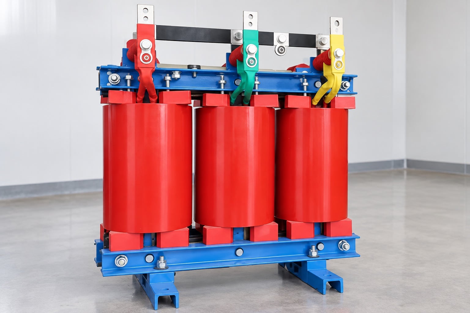
Cable routing, phase identification and grounding
Plan entry direction and bending radius before cutting the cable. Phase conductors should approach their terminals without crossing unnecessarily or applying side load. Maintain separation from low-voltage control wiring and temperature-sensor circuits. Identify phases consistently at both ends and check the system phase sequence before energization. Metallic cable screens, armor and gland plates must be bonded or grounded according to the approved system design; bonding choices affect induced voltage and circulating current.
Where single-core AC cables pass through metal plates, the gland arrangement must avoid unintended magnetic heating. Nonmagnetic plates or appropriately grouped phase openings may be required by the design. Fire stopping should restore the required barrier without damaging cable insulation. The enclosure must also preserve the ventilation path on which the dry transformer rating depends. The dry-type transformer clearance guide explains why walls, cable boxes and airflow must be coordinated.
A controlled installation sequence
- Authorize and isolate. Confirm the correct asset, de-energize, lock out, verify absence of voltage and apply grounding where the site’s procedure requires it.
- Inspect materials. Check cable, kit, lugs and terminals against approved drawings and shelf-life or storage requirements.
- Set supports. Establish the route, cleats and bending radius before final conductor preparation.
- Prepare the cable. Qualified jointers follow the exact kit dimensions and use clean, controlled tools.
- Make the interface. Install the connector and bolt it to the transformer terminal using the approved method and recorded torque where specified.
- Restore insulation and sealing. Complete stress control, grounding, boots, barriers, glands and fire stopping.
- Inspect and test. Verify phase identity, clearances, supports, bonding, joint condition and specified electrical tests before energization.
Cleanliness is especially important for medium-voltage accessories. Dust, moisture, nicks, uneven screen cutbacks or trapped contamination can create localized electrical stress. If preparation is outside the kit tolerance, stop and replace the affected material rather than disguising the defect.
Inspection and electrical testing
A pre-energization inspection should confirm that terminal hardware is complete, lugs are fully seated, no cable force is transferred to the terminal, phase barriers are present, clearances match the drawing and the enclosure contains no debris or tools. Record conductor identification, kit batch information where required, jointing personnel, torque records and photographs permitted by the quality plan.
Testing must be agreed by the transformer, cable and accessory suppliers. Insulation-resistance, continuity, phase identification and sheath tests may be appropriate, but test voltage and method depend on the installed system. An unsuitable DC or AC withstand test can overstress equipment. Coordinate any cable test with connected surge arresters, instrument transformers and electronics. Transformer ratio and winding-resistance tests address different questions; see the transformer turns-ratio test guide.
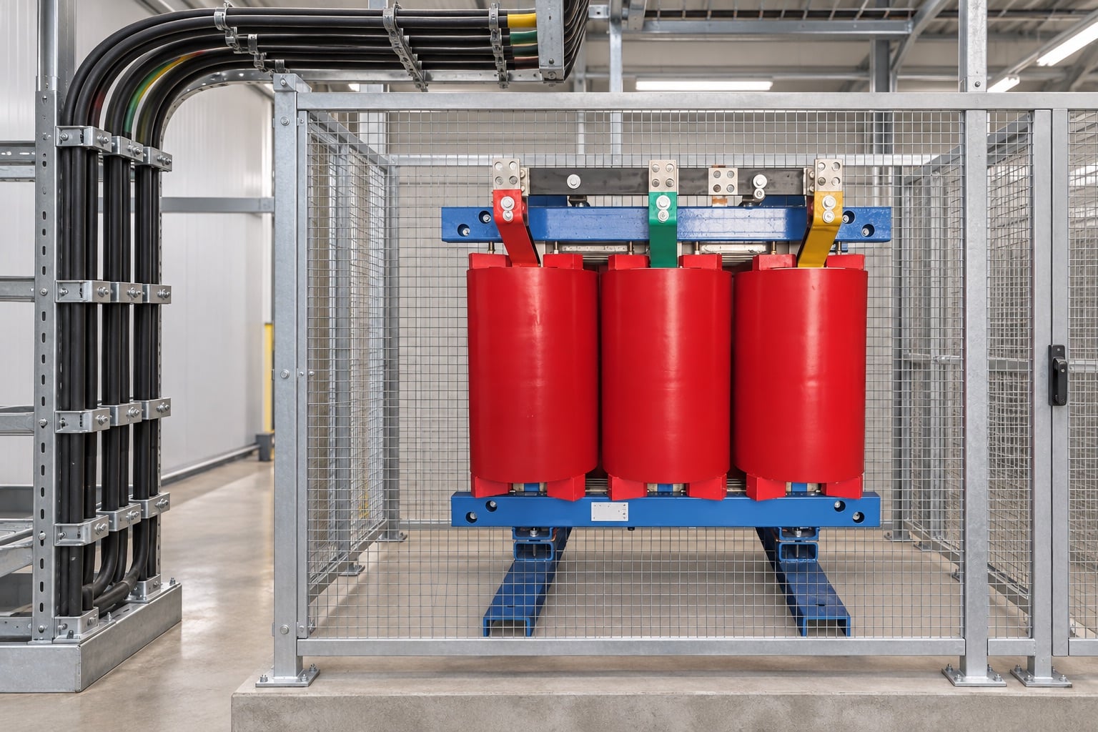
Commissioning and first-load checks
Before energization, close all approved covers and barriers, clear personnel and follow the site’s switching program. Confirm protection settings, temperature sensors, fans if fitted and alarms. On initial energization, monitor for abnormal sound, odor, discharge indications or protection operation from a safe location. Increase load only under the commissioning plan.
After the installation has operated at a stable representative load, qualified personnel may perform an external thermal survey using the site’s electrical-safety rules. Compare equivalent phases and joints while recording current and ambient conditions. A thermal camera cannot see through an opaque closed panel, and a bright color alone is not an acceptance limit. Trends and asymmetry should trigger an engineering review, not unplanned access to energized terminals.
Procurement checklist
- Transformer terminal drawing, enclosure and cable-entry details.
- Cable schedule with voltage class, conductor, insulation, screen and dimensions.
- Approved termination kit and lug compatibility evidence.
- Required clearances, phase barriers, glands, supports and bonding design.
- Manufacturer’s fastener and tightening instructions.
- Inspection and test plan agreed across transformer, cable and accessory suppliers.
- Installation records and as-built photographs or drawings.
Handover documents and maintenance baseline
The handover package should give maintenance personnel enough information to reproduce the approved connection. Include the final terminal drawing, cable schedule, accessory instructions, material certificates required by the contract, torque record, test results and photographs showing supports before covers were fitted. Mark any deviation accepted during installation. Establish a baseline thermal image when a representative stable load is available and retain the current and ambient conditions with it. During future outages, inspect for discoloration, contamination, cracked insulation, loose supports and evidence of movement. Any change to cable size, number of parallel runs, enclosure or terminal hardware must be reviewed as an engineering change rather than treated as routine replacement.
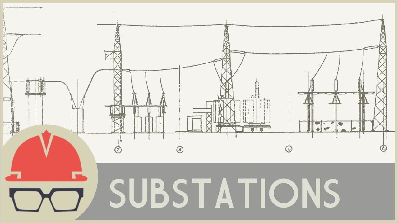
Video: substation equipment context
This independent explainer shows how transformers and switchgear fit within a substation. It does not replace a termination kit instruction or the site’s safety procedure.
Soalan Lazim
Can any lug be used on a dry type transformer?
No. It must match conductor material and size, terminal geometry, current duty and the manufacturer’s approved joint arrangement.
Should the cable weight hang from the transformer terminal?
No. Independent cleats and supports should restrain the cable and fault forces so the terminal is not mechanically loaded.
Can a completed cable be tested while connected to the transformer?
Only under an approved method coordinated with all connected equipment suppliers. Test voltage and isolation requirements are system-specific.
What records should be retained?
Keep approved drawings, material identification, preparation and torque records, inspection results, test reports and as-built changes.