Depuis 2001, Shenheng Power est un fabricant de confiance d'équipements de transmission et de distribution d'énergie, fournissant des solutions électriques fiables à l'échelle mondiale.
Forts d'un système complet de service après-vente, nous fournissons des conseils techniques d'experts, des conseils sur les produits et des services OEM et ODM flexibles pour vos projets.
Depuis 2001, Shenheng Power est un fabricant de confiance d'équipements de transmission et de distribution d'énergie, fournissant des solutions électriques fiables à l'échelle mondiale.
MV Switchgear Cable Clamp Replacement: Verify the Support Arrangement
Release Time: 2026-11-17
An MV switchgear cable clamp replacement review should verify the cable, clamp, mounting rail and supporting structure together. A matching cable diameter does not prove that a spare can retain the cable under its declared loads or preserve the original termination layout. Identify the assembly and cable circuit, obtain the approved support drawing, and ask the responsible manufacturers to confirm the proposed replacement. This guide is a planning checklist for engineers and buyers. It gives no instructions for entering an energized cable compartment, loosening cable supports or changing a medium voltage termination.
Identify what the component actually does
A cable support can carry weight, limit movement or contribute to restraint against electromechanical forces. A gland, temporary positioning aid and tested cable cleat do not automatically perform the same function. Start by identifying the component on the original drawing, rather than calling every piece of cable hardware a clamp.
Record the switchgear serial number, panel designation and cable circuit. Establish where the support lies relative to the termination, gland plate, cable route and any current transformer. A photograph from another panel may show a similar part but a different cable arrangement. Confirm that all evidence refers to the same location.
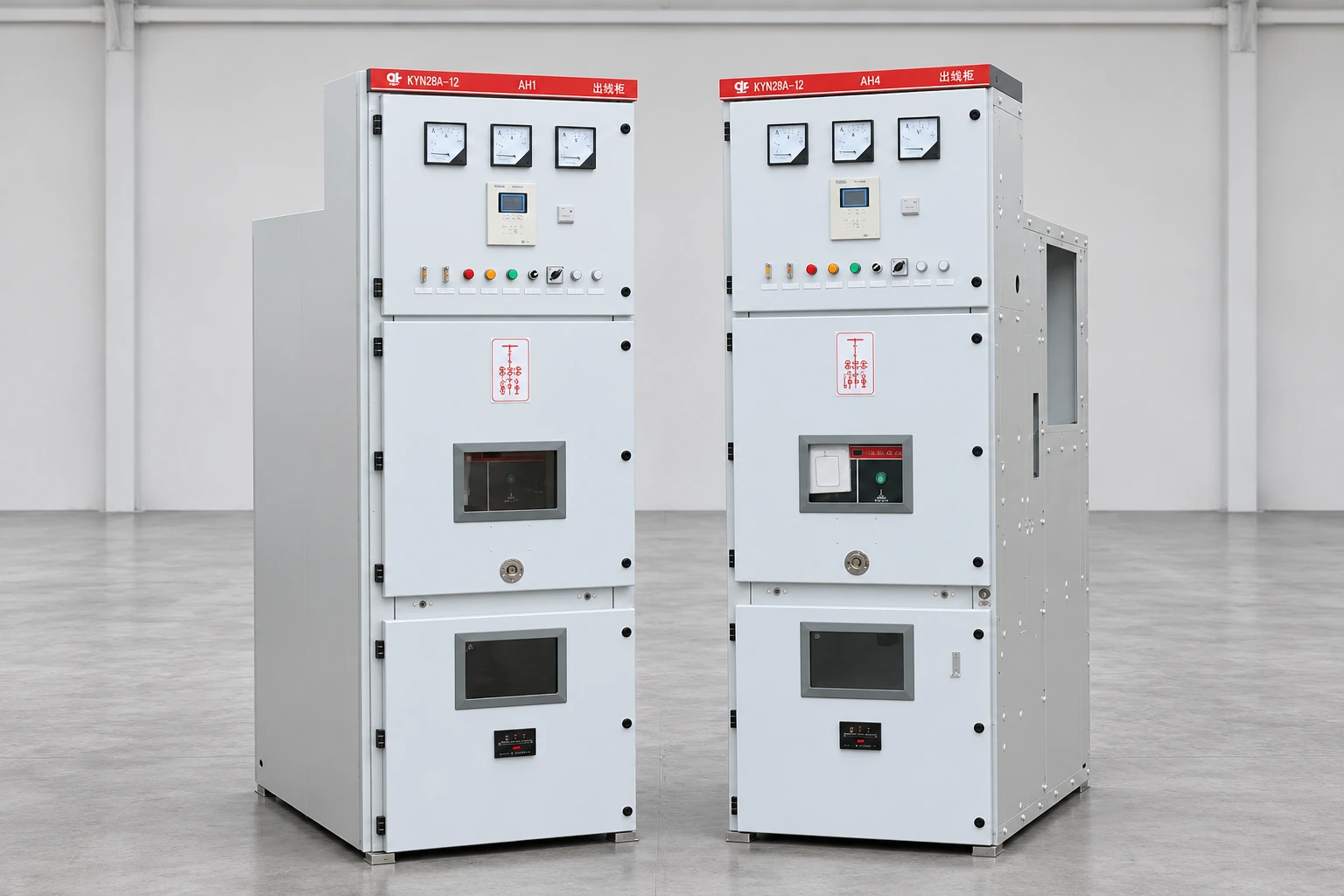
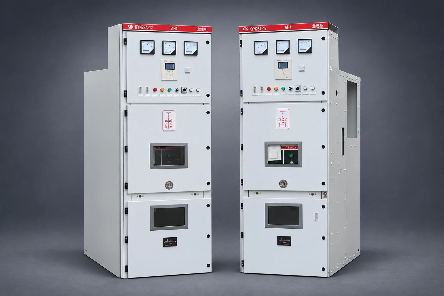
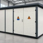
Shenheng’s medium voltage switchgear product is the relevant product-family reference. Its external photograph does not establish the cable compartment geometry, the installed cable supports or whether a specific cleat was supplied. The closed-cabinet illustration is contextual; actual compatibility must come from the named assembly’s documents.
Illustration de référence du produit basée sur l'image du produit Shenheng ; il ne s'agit pas d'un enregistrement réel de maintenance, de test ou de site client.
Understand what IEC 61914 can establish
Le responsable IEC 61914:2021 publication scope covers cable cleats and intermediate restraints. It distinguishes securing cables from holding them together in formation and refers to resistance to electromechanical forces where declared. It also recognizes that the mounting surface specified by the manufacturer can form part of the retention arrangement.
That scope is not a certification statement for every component sold as a clamp. Request the applicable manufacturer declaration and evidence for the proposed part and installation. A description that simply says “IEC compliant” does not identify which properties were declared or whether the mounting conditions match the switchgear.
Do not invent a universal support spacing or fault-current rating from the name of the standard. The relevant evidence must connect the specific cable formation, cleat model, fixing arrangement and supporting structure to the application. The responsible engineer determines what design or test evidence is sufficient for the actual duty.
Separate the cable restraint review from termination selection
The termination controls the electrical interface at the cable end. The support arrangement controls how mechanical loads and movement are managed along the cable route. They interact, but approval of one does not establish approval of the other.
Utilisez le MV cable termination guide for the separate termination enquiry. In a clamp replacement review, identify whether the existing termination or cable position will be disturbed. If the proposed spare changes the cable centreline, its distance from the terminal or the shape of a bend, the original termination acceptance cannot simply be assumed to remain applicable.
For the wider assembly context, see the Guide sur les équipements de commutation à moyenne tension. The following review is deliberately narrower than switchgear selection: it asks how to preserve an existing approved cable support arrangement during a defined component replacement.
Build a cable and support data sheet
Identify the actual cable manufacturer and designation. Record the outside diameter relevant to the clamp, number of cables per phase, formation, sheath construction and the location of joints or accessories. Conductor cross-sectional area alone does not establish outside diameter, and two cables with similar current ratings may need different supports.
Obtain the support rail drawing, material and mounting details. Identify the load path through the cleat, fasteners, rail and attachment to the cabinet. A strong replacement cleat on an unverified rail does not establish that the arrangement is adequate. Include any approved liners, inserts, spacers or secondary restraints in the bill of materials.
The table is an original review checklist using the IEC scope and HSE electrical work planning guidance as context. It does not supply design limits or substitute for the equipment instructions.
Évaluation de l'article
Des preuves nécessaires
Reason to withhold approval
Component function
Original drawing and manufacturer designation
A positioning clamp is assumed to be a fault restraint
Cable compatibility
Actual cable diameter, construction and formation
La sélection est basée uniquement sur la section du conducteur
Retention duty
Relevant declaration and supporting application evidence
Declared duty cannot be linked to the proposed arrangement
Mounting surface
Rail, brackets and cabinet fixing details
Cleat strength is known but the load path is not
Fixings and inserts
Approved hardware, liner and tightening instructions
Unspecified bolts or improvised packing are proposed
Electrical interfaces
Termination, screen and current-transformer layout
cURL Too many subrequests by single Worker invocation. To configure this limit, refer to https://developers.cloudflare.com/workers/wrangler/configuration/#limits
cURL Too many subrequests by single Worker invocation. To configure this limit, refer to https://developers.cloudflare.com/workers/wrangler/configuration/#limits
cURL Too many subrequests by single Worker invocation. To configure this limit, refer to https://developers.cloudflare.com/workers/wrangler/configuration/#limits.
cURL Too many subrequests by single Worker invocation. To configure this limit, refer to https://developers.cloudflare.com/workers/wrangler/configuration/#limits.
cURL Too many subrequests by single Worker invocation. To configure this limit, refer to https://developers.cloudflare.com/workers/wrangler/configuration/#limits.
cURL Too many subrequests by single Worker invocation. To configure this limit, refer to https://developers.cloudflare.com/workers/wrangler/configuration/#limits
cURL Too many subrequests by single Worker invocation. To configure this limit, refer to https://developers.cloudflare.com/workers/wrangler/configuration/#limits.
If a supplier proposes a new arrangement, require the assumptions to be visible. A test report for a different cable formation or support surface may not settle the question. The engineer should explain how the evidence applies or request a more appropriate solution before procurement release.
Illustration de référence du produit basée sur l'image du produit Shenheng ; il ne s'agit pas d'un enregistrement réel de maintenance, de test ou de site client.
Protect the cable, screens and nearby equipment
A support must not create an unreviewed problem for the cable sheath or termination. Confirm the permitted contact arrangement and any required inserts with the cable and support manufacturers. Avoid improvising cushioning material because it looks protective; its properties and suitability may be unknown.
Review the original screen bonding and earthing route. A clamp replacement should not casually move screen conductors, change a current-transformer arrangement or trap a connection against an edge. Where those interfaces are affected, extend the approved technical scope and identify the required verification before work starts.
The compartment may also contain barriers, shutters or mechanisms with their own required clearances. The switchgear shutter mechanism review addresses that separate assembly function. Its relevance here is coordination: the cable support repair must not interfere with adjacent equipment, and any discovered defect should be recorded under the appropriate work scope.
Prepare the outage and acceptance plan
Plan electrical safety and physical cable support together. Qualified personnel must determine how all relevant sources are controlled and how the cable remains safely supported during the authorized work. This article intentionally omits a support-removal or clamp-tightening sequence.
Le HSE maintenance guidance emphasizes competent maintenance and safe isolation. Apply the actual site rules and equipment instructions, including any requirements for stored energy, connected circuits and access restrictions. De-energization alone does not establish every condition needed for mechanical work.
Before the outage, agree on the acceptance record. It should identify the installed part, fixings, inserts, drawing revision and manufacturer instructions used. Define the visual, dimensional and any required electrical checks for the work performed. There is no universal torque, cable movement allowance or test voltage in this guide.
Know when to stop the spare order
Hold technical approval when the cable identity is uncertain, the support drawing is missing, the proposed part changes the load path or the supplier cannot link its declaration to the installation. These are specific information gaps that can be resolved through a drawing review, site survey or manufacturer response.
Also investigate why the existing component needs replacement. A broken support can be a symptom of another problem, including an installation mismatch or an event requiring wider assessment. Replacing the broken part without reviewing the cause may leave the underlying condition unchanged.
A usable request for quotation includes the assembly and cable identities, support drawing, photographs, original part number, failure description and required scope. Ask for a complete compatible set where inserts or fixings are essential. State that substitutions require review and request the evidence needed to accept the restored arrangement.
Safety learning before planning the work
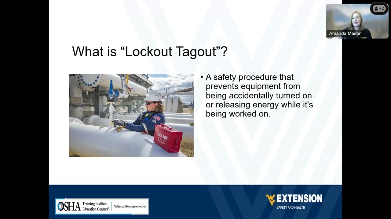
The US Department of Labor video below introduces lockout and tagout. It supports the need to control hazardous energy during maintenance. It does not authorize entry to medium voltage switchgear or replace the project’s isolation and cable-support work plan.
Pour approfondir : Stand Up For Safety and Health – Consignation et déconsignation (Lockout/Tagout) — Ministère du Travail français. Disponible sur YouTube.
Foire aux questions
Can a cable clamp be selected from conductor size alone?
No. Actual cable dimensions, construction, formation, support function and mounting arrangement matter. Obtain the relevant cable data and manufacturer-approved support details before selecting a replacement.
Does an IEC 61914 reference prove short-circuit suitability?
No. Review the declared properties and supporting evidence for the actual part and configuration. The standard’s name alone does not establish that a particular installation has the required restraint performance.
Must the mounting rail be included in the review?
Yes. Loads pass through the cleat, fixings and supporting structure. Evidence for a cleat does not automatically establish the adequacy of a different rail or cabinet attachment.
What should be retained after replacement?
Keep the compatibility approval, part and hardware traceability, controlled drawing, work record and required acceptance results. Record any changes to cable routing or adjacent interfaces and who approved them.
Shenheng Electric Power s'engage à devenir un leader mondial des solutions d'équipements électriques, aidant les clients à réaliser une gestion de l'énergie sûre, efficace et durable.

 Shenheng Power Equipment Co., Ltd.