
 Shenheng Power Equipment Co., Ltd.
- Home
- Products
Products
Since 2001, Shenheng Power has been a trusted manufacturer of power transmission and distribution equipment, delivering reliable electrical solutions globally.

- Solutions
- News & Blog
- Service
- About Us
- Contact Us
Since 2001, Shenheng Power has been a trusted manufacturer of power transmission and distribution equipment, delivering reliable electrical solutions globally.
Substation lightning protection combines interception of direct strikes, controlled current paths, grounding and protection against surges entering through connected circuits. A mast or overhead shield wire addresses a different problem from a surge arrester, and neither independently provides complete protection. Design begins with the actual substation layout, incoming lines, equipment insulation, site conditions and acceptable risk. The resulting arrangement must be coordinated with the grounding and insulation studies. Generic mast spacing, a single earth-resistance target or an arrester installed without lead-layout review is not a complete design.
Direct strikes can reach equipment or structures inside the substation. Surges can also arrive through overhead circuits, cable transitions or other connected services. Low-voltage controls and communications may be affected through their own interfaces. These paths need related but distinct measures.
Create a layout that identifies exposed equipment, incoming circuits, structures and cable routes. Include elevations because shielding depends on the three-dimensional arrangement. Record buildings, fences and future extensions rather than assessing only the initial transformer footprint.
Use the substation single-line diagram guide to establish the electrical connections, then combine it with the physical layout. A single-line drawing alone cannot show shielding coverage or conductor routing, while a site drawing alone cannot explain the electrical surge paths.
| Measure | Main function | Design questions | Evidence for acceptance |
|---|---|---|---|
| Masts or shield wires | Intercept direct lightning strikes | Does the validated method cover equipment elevations? | Shielding study and layout |
| Down conductors and bonds | Provide defined paths toward the grounding system | Are paths continuous and coordinated with clearances? | Drawings and inspection record |
| Grounding system | Manage current distribution and accessible potentials | How do soil and fault conditions affect the design? | Grounding assessment and site tests |
| Surge arresters | Limit specified overvoltage exposure at protected equipment | Are rating, duty, location and leads coordinated? | Insulation-coordination study |
| Control-circuit surge protection | Address relevant low-voltage entry paths | Which interfaces cross exposure boundaries? | Interface schedule and coordinated selection |
| Inspection program | Preserve the intended arrangement | Can connections, corrosion and changes be detected? | Maintenance plan and as-built records |
This table is a functional comparison without universal dimensions. NPTEL’s lightning protection teaching material helps distinguish shielding and arrester functions. It does not replace a site-specific design study.
An interception system is designed using an appropriate engineering method and the risk assumptions adopted for the project. Mast height, protected equipment height and horizontal distance interact. A simple circle drawn around a mast without an identified method is insufficient evidence of coverage.
Consider the complete operating layout. Include elevated bushings, overhead connections, structures and any equipment added later. If a transformer is replaced by a taller unit, the existing shielding assessment may need revision even when its electrical rating is similar. Future expansion should be identified as a design input, not assumed to fit inside the initial coverage.
Review mast position against electrical clearances, mechanical loads, maintenance access and foundations. The lightning system should not create an unacceptable proximity to energized conductors or obstruct an equipment replacement route. The civil and electrical drawings need to agree on the installed position and height.
A grounding system distributes lightning and fault currents while addressing accessible potential differences. Soil properties, seasonal conditions, grid geometry, connections and current paths all affect its behavior. A measured resistance value can be useful, but it does not by itself prove acceptable touch or step conditions.
The grounding designer should identify the project assessment method and relevant current conditions. Review fences, gates, buildings, cable screens, masts and equipment bonding as part of one system. Separate metallic services can introduce additional paths that must be considered rather than left as independent contractor details.
OSHA’s protective-grounding guidance is a useful safety reference for the importance of potential differences in work areas. Its construction-work requirements do not constitute a universal substation lightning-grid design rule. Use the applicable local rules and project standards for the permanent grounding system.
An arrester must be selected for the network operating voltage, grounding arrangement and temporary-overvoltage duty, as well as the intended surge exposure. The protected equipment’s insulation withstand characteristics form the other side of the coordination. An arrester voltage designation alone does not establish an adequate protection margin.
Identify the points where surges enter and the equipment most exposed. Examine overhead-to-cable transitions and transformer terminals as part of the system rather than choosing locations from convenience. The study should explain the intended protection at each location and any assumptions about incoming waves or switching events.
Use the substation grounding-system guide to organize the site current-path and connection questions. Keep the arrester schedule connected to the overall lightning design so different contractors do not choose incompatible arrangements.
The installed connection between an arrester, the protected terminal and the grounding system influences the voltage experienced by the equipment during a fast event. Long or indirect paths can reduce the value of an otherwise appropriate arrester selection. Evaluate the actual routing rather than assuming that an arrester symbol on a drawing settles the issue.
Coordinate leads with physical clearances, mechanical support and inspection access. Avoid creating loops or routes that differ from the study assumptions without review. Cable screen and equipment bonding arrangements also need to match the approved design and the specified termination method.
Require as-built photographs and drawings of the critical connections. If site constraints force a relocation, ask the designer to evaluate the change before accepting it. A useful acceptance record shows the final installation dimensions and routes, not only the purchase specification.
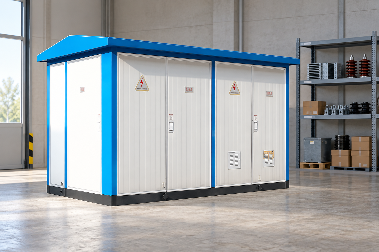
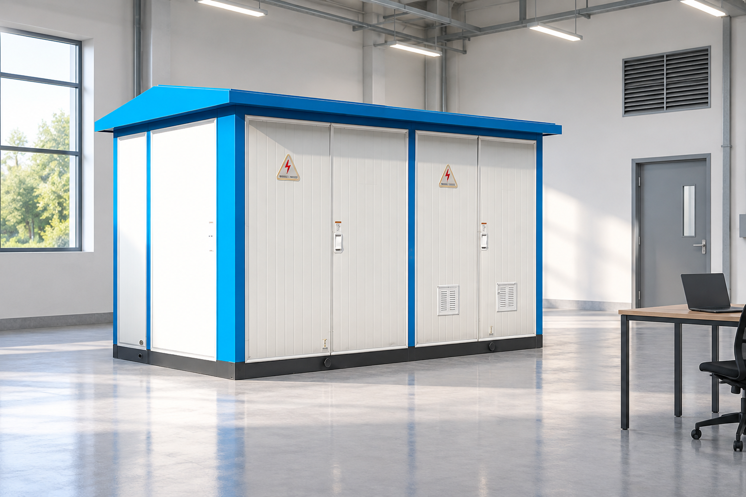
A compact outdoor substation brings equipment into an enclosure, but its protection depends on the incoming circuits, site grounding and complete installation. The enclosure does not automatically eliminate surge entry or establish coverage against every direct-strike scenario.
Ask the supplier to identify what is factory provided and what remains a site responsibility. Clarify arrester locations, bonding terminals, cable entries, any required external shielding and the applicable installation limits. A division-of-supply document should assign each interface to a named party.
The indoor versus outdoor substation comparison helps describe location choices, but it is not a substitute for lightning assessment. Indoor equipment can still receive incoming surges, and outdoor equipment can be well protected when the complete arrangement is correctly designed.
Identify copper communication cables, instrument circuits, auxiliary power supplies and any external control connection. A surge can affect these interfaces differently from the main power circuit. Describe where each cable enters a building or cabinet, its shielding arrangement and the devices connected at both ends.
Coordinate surge-protective devices with signal requirements, operating voltage and the grounding arrangement. A device selected only because it is labeled for lightning may interfere with a signal or provide incomplete protection. The responsible designer should confirm the permitted interface characteristics and failure behavior.
Fiber can reduce some conductive paths, but it does not remove the need to assess power supplies, metallic cable elements and associated equipment. Review the complete interface rather than assuming that one fiber connection makes every part of a control system independent of lightning effects.
During commissioning, verify mast locations, bonding, visible conductor continuity and critical connection routes against the approved drawings. Record site grounding tests using the project’s method and conditions. Inspect damage, loose hardware or missing connections before energization.
The maintenance plan should address corrosion, mechanical damage, disconnected bonds, arrester indications where provided and alterations to the layout. After a significant event or unexplained failure, collect evidence before replacing equipment. The location of damage, event records and weather information can help the engineer understand the path involved.
Keep a change register. New fences, rooftop equipment, extensions, moved arresters or revised cable routes can change the original assumptions. Review those changes together with the protection-zone arrangement, since physical protection and fault-clearing boundaries must remain understandable to operators.
Provide site coordinates, relevant weather and exposure information, soil data, layout elevations, incoming circuit details and equipment insulation information. State the design method and project standards required by the owner. Ask the designer to identify missing inputs and the sensitivity of the result to assumptions.
Request shielding coverage drawings, grounding interfaces, arrester schedules, lead-layout requirements, control-interface protection and maintenance instructions. Require the final package to identify exclusions and future expansion assumptions. A single note saying “lightning protection by others” is inadequate when the interfaces affect factory equipment.
Further learning: Insulation Co-ordination in Power System Engineering |High Voltage Engineering Lecture Series |BIL — Simplified EEE Studies. This educational video supports the topic; it is not a product demonstration or an operating authorization. Open the video on YouTube.
No. It addresses direct-strike interception under defined geometry. Incoming surges, grounding, bonding and control interfaces still need coordinated measures.
No. Resistance is one measurement. Current paths, grounding geometry, potential differences and equipment coordination must also be assessed.
Only after reviewing the protection and connection assumptions. Location and lead routing affect the installed result, so changes need engineering acceptance.
Yes. The supplier’s equipment and the site’s incoming circuits, grounding and exposure must be coordinated. Factory supply boundaries should be documented clearly.






