
 Shenheng Power Equipment Co., Ltd.
- Home
- Products
Products
Since 2001, Shenheng Power has been a trusted manufacturer of power transmission and distribution equipment, delivering reliable electrical solutions globally.

- Solutions
- News & Blog
- Service
- About Us
- Contact Us
Since 2001, Shenheng Power has been a trusted manufacturer of power transmission and distribution equipment, delivering reliable electrical solutions globally.
Substation cable trench design coordinates cable routes, accessible supports, structural covers and drainage so that cables can be installed, inspected and replaced without directing water or spilled transformer oil into equipment buildings. Start with the approved cable schedule and site levels, then verify bends, segregation, pulling access, crossings and future capacity. There is no universal trench width, depth or drainage slope suitable for every station. The responsible electrical and civil designers must agree these details with the asset owner and equipment supplier. This guide provides a design-review sequence for buyers and project teams, rather than construction dimensions or permission to work on live equipment.
A trench is part of the cable system, not simply an empty concrete channel. Its purpose depends on the circuits it carries: protection and control cables, communication circuits, auxiliary supplies, or power cables can have different installation and separation needs. Record circuit functions before choosing a shared route. A neat-looking arrangement can still be unsuitable if redundant protection paths share an avoidable common hazard or if electromagnetic interference has not been assessed.
For a compact outdoor electrical substation, confirm the actual cable entry positions and foundation openings using the supplier’s approved drawings. A product photograph does not establish whether entry is underneath, from the side, or through a particular compartment. Freeze the interface before pouring the foundation. Otherwise, an apparently minor cabinet change can require expensive demolition or force cables into unacceptable bends.
Read the compact substation layout checklist alongside the trench review. The overall layout determines whether the route conflicts with maintenance access, equipment replacement paths, earthing conductors or site drainage. Assign one owner to each interface and obtain written agreement before construction.
List each cable’s identifier, destination, construction, outside diameter, mass and installation restrictions. Obtain the manufacturer’s minimum bending radius and pulling limitations for the relevant installation condition; these may differ between pulling and final placement. Do not replace them with a generic multiplier found in an unrelated drawing. Record any cable support requirements and the arrangement used in the electrical rating calculation.
The civil inputs should include surveyed levels, soil and groundwater conditions, traffic loads, flood exposure and proposed outfalls. Include access requirements for cover removal, local lifting equipment and cable replacement. If a trench crosses a delivery road, its structural design must address the actual loading case, not only pedestrian access. Ask the structural engineer to identify the cover class and supporting details on the drawings.
Describe future provision explicitly. An empty strip of floor is not useful spare capacity when the next cable cannot pass a corner or rise into the panel. Reserve accessible support positions, termination space and workable pulling routes together. Document the expansion assumption so that the buyer can compare proposals on the same basis.
Draw the full path from the cable entry at one end to the termination at the other. Review corners, branch junctions, changes in elevation and equipment approaches. A straight main trench can hide a tight bend immediately below a cabinet. Show sections through the difficult points and coordinate them with the equipment supplier rather than approving the plan view alone.
Keep cable routes away from predictable damage and spill paths where practicable. Transformer oil release, vehicle movement and construction excavation should appear in the route-risk review. A covered trench must not become an easy path for released oil to reach a control building. Fire and environmental engineers should agree any barriers or drainage isolation needed at these interfaces.
Separate redundant circuits where required by the protection philosophy and owner specification. Physical separation, shielding, bonding and circuit routing address different risks and should not be treated as interchangeable. Record the decision for each relevant cable group and preserve the same arrangement in the installed records.
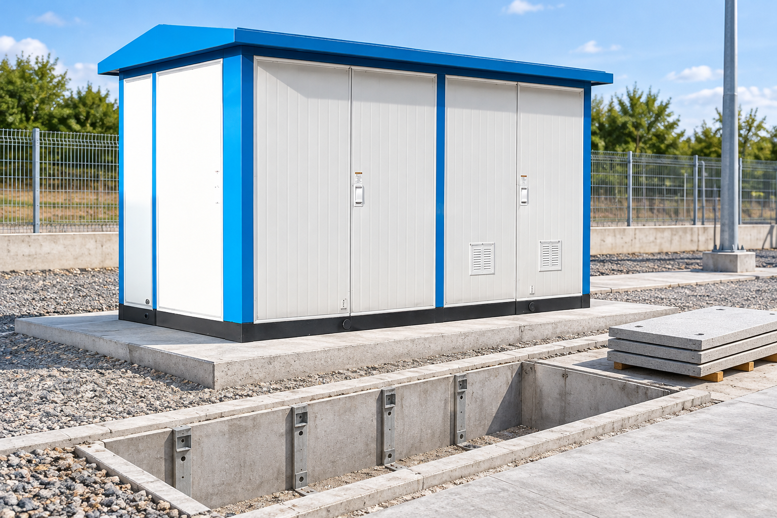
Width and depth follow the selected support layout and access method. Include cables, racks, brackets, vertical clearances, cable crossing zones and the space needed to handle a replacement cable. Check that supports can carry the installed weight and anticipated future additions. The structural load capacity of a rack does not establish the electrical current-carrying capacity of the cables on it.
For power circuits, verify thermal performance using the actual cable grouping and installation environment. Close packing, multiple layers and nearby heat sources may affect permissible loading. For control and communication cables, maintain the separation and shielding arrangement required by the project. Do not assume that a broad trench automatically solves electrical interference or heat dissipation.
Use a section drawing showing the proposed arrangement rather than relying on an overall internal dimension. Identify occupied and reserved support positions separately. At junctions, check whether branches cross other circuits and whether there is sufficient space to preserve bending limits. A trench suitable along its straight length can fail at the first intersection.
Drainage must have a defined collection path, low points and discharge destination. Survey the trench invert and the building entry level together. Where gravity drainage is proposed, demonstrate that the receiving system can accept the flow under the design conditions and will not send water back into the trench. Groundwater and flooding require separate assessment from ordinary surface rain.
The owner-specific ElectraNet substation cable requirements discuss trench slope, sumps and coordination with stormwater drainage. Those requirements are useful design-review evidence, but their dimensions and slopes belong to that owner’s application and must not be copied as universal rules. Confirm the current contractual specification for your project.
Distinguish clean site water from potentially contaminated water. Do not connect transformer spill areas directly to cable trenches or ordinary stormwater outlets without an approved environmental design. Where pumping is necessary, address power availability, alarms, inspection access, maintenance and the consequence of failure. A pump symbol on a drawing is not proof that a low point will remain dry during a storm or power outage.
Protect building entries against water migration using the approved arrangement. Sealing, drainage and levels must work together, while preserving cable fire protection and replaceability. Record the inspection method for the completed penetration, including how inaccessible portions will be checked before they are concealed.
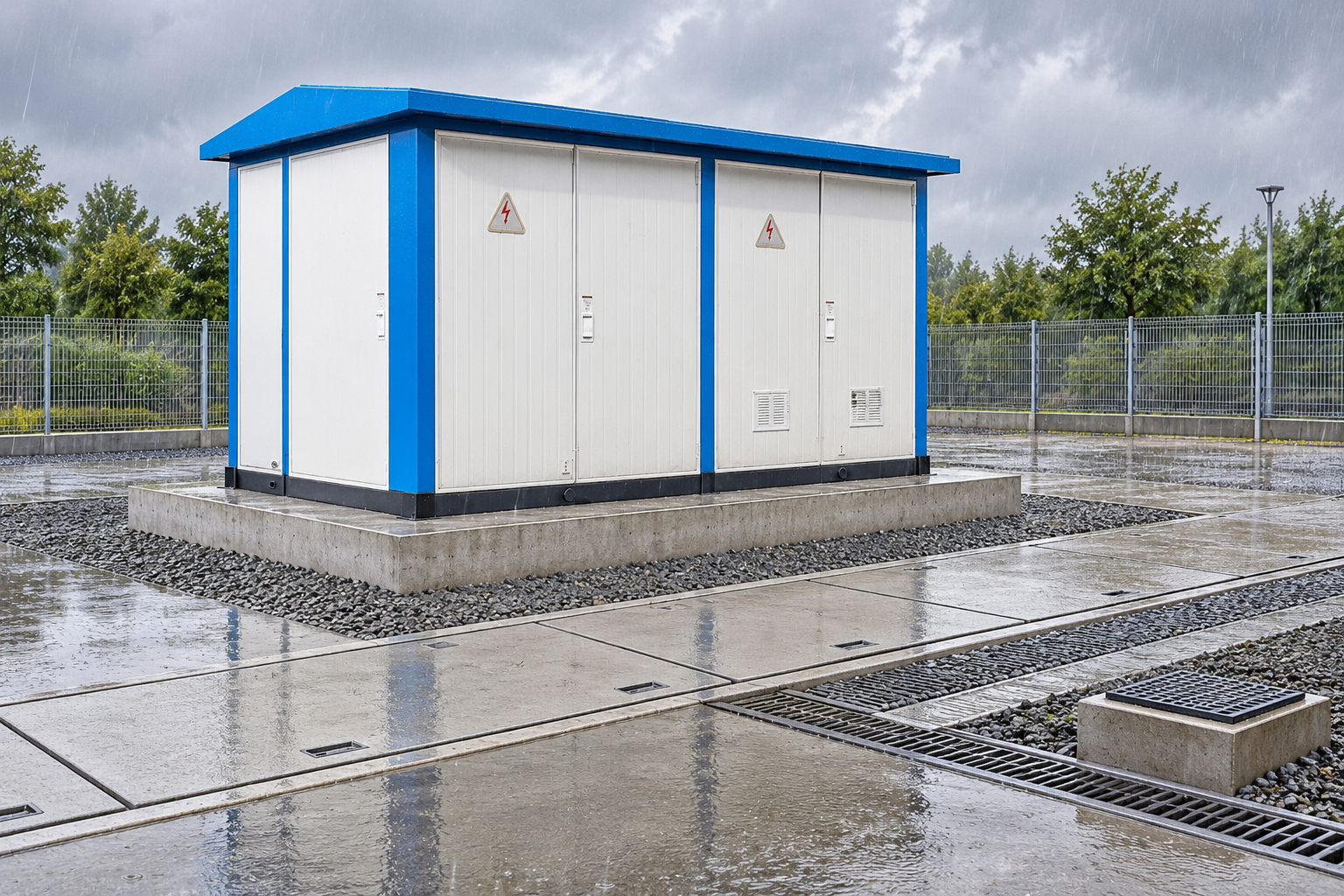
Specify cover material, loading duty, lifting arrangements and seating details. Covers should be removable using the planned method without disturbing cables or creating uncontrolled openings in a working route. Check that adjacent covers can be lifted where required, and that stored covers will not obstruct emergency access. Damaged or rocking covers require correction before handover.
Plan support materials and fixings around the environment. Moisture, corrosion exposure and dissimilar materials can affect serviceability. Support spacing and attachment details must follow the cable and rack design; field improvisation can damage the cable sheath or overload a bracket. Record any required bonding of metallic parts and obtain the electrical designer’s approval of the final arrangement.
Before personnel enter or open any part of the installation, apply the site’s electrical safety and work-control procedures. Isolation, confined-space assessment and fall protection depend on the specific trench and work activity. This article does not establish that a trench is safe to enter or that adjacent equipment is de-energized.
The following table is a qualitative review aid. It draws on cable-system considerations in the IEEE 525 guide available through IEEE’s substation working group and the owner requirements above. The archived IEEE document is background material; the contract must identify the applicable current edition and requirements.
| Review item | Evidence to request | Approval question |
|---|---|---|
| Equipment entry | Supplier foundation and cable-entry drawings | Can every cable enter without violating its installation limits? |
| Routing | Cable schedule, route plan and difficult-point sections | Are segregation, replacement access and common hazards addressed? |
| Supports | Rack layout, load calculation and fixing details | Are present and planned cables supported safely? |
| Electrical rating | Calculation using actual cable grouping and environment | Does the installed arrangement match the rating assumptions? |
| Drainage | Levels, low points, outfall assessment and pump logic if needed | Where does water go, and what happens when the system fails? |
| Covers and crossings | Structural design and removal method | Are loads and maintenance access both accommodated? |
| Building penetration | Approved water and fire barrier details | Can seals be inspected and cables replaced as intended? |
Set hold points before concrete placement, cover installation and cable pulling. Check trench alignment, levels, reinforcement and embedded items against the approved drawings at the relevant stage. Photograph interfaces and record measurements rather than depending on a general completion photograph. Correct inaccessible defects before the next trade covers them.
Before pulling cables, remove sharp edges, debris and standing water; inspect supports and confirm pulling access. Agree the pulling method with the cable supplier and installation team. After installation, verify identification, bend condition, support placement, grouping and entry seals. Preserve test and inspection records with the cable schedule.
During acceptance, test drainage using an agreed safe method and observe the actual flow path. Check low points and investigate residual ponding. Review any pump controls and alarms under an authorized test procedure. Use the site acceptance test checklist to coordinate equipment checks, while keeping trench civil acceptance and cable testing clearly assigned.
A comparable enquiry should include the route drawings, cable schedule, site conditions, load cases, expansion assumptions, drainage basis and interfaces requiring supplier confirmation. Ask tenderers to state exclusions explicitly. A low price that excludes covers, supports, pumping or building seals cannot be compared directly with a complete system offer.
The handover file should contain approved revisions, surveyed as-built levels, cable identifiers, support details, drainage destinations, inspection results and maintenance access instructions. Include a method for recording later additions. Future installers need to know the original thermal and segregation assumptions before occupying apparently spare space.
Coordinate the handover with the switchgear factory acceptance checklist. Factory inspection can establish the equipment interface, but it cannot prove that the site trench was constructed correctly. The final approval should connect both evidence sets.
The following educational video reviews cable trenches, supports and trays. It provides background terminology for design discussion; project drawings, supplier limits and authorized site procedures govern the actual installation.
Further learning: Cable Trench, Cable Support Structure & Cable Tray (Knowledge of Civil & Electrical Engineering) — Engineer Khurshid. Educational background; this is not an operating authorization. Open the video on YouTube.
The cable schedule, support arrangement, bends, segregation, thermal assumptions, structural requirements and replacement access determine usable dimensions. Review sections and difficult junctions as well as the straight route.
Only when the approved drainage and environmental design permits it. Assess backflow, flooding and contamination routes, especially near oil-filled equipment, and confirm the outfall conditions.
No. The project designer must select levels and slopes around the actual route, groundwater, outfall and owner requirements. A value in one utility specification is not a universal rule.
Verify the as-built route and levels, covers, supports, cable arrangement, identification, entry seals and demonstrated drainage function. Preserve inspection records and the assumptions governing future cable additions.






