Shenheng Power Equipment Co., Ltd.
- Home
- Products
Products
Since 2001, Shenheng Power has been a trusted manufacturer of power transmission and distribution equipment, delivering reliable electrical solutions globally.

- Solutions
- News & Blog
- Service
- About Us
- Contact Us
Since 2001, Shenheng Power has been a trusted manufacturer of power transmission and distribution equipment, delivering reliable electrical solutions globally.
Buyers evaluating ring main unit protection for utility, industrial, or renewable cable networks need a practical way to align fuse or breaker schemes, CT ratios, relay settings, and feeder fault studies before energization.
This guide summarizes decision steps used by EPC teams and protection engineers when they coordinate ring main unit protection with the approved single-line diagram and utility interconnection rules. Use it as a procurement checklist—not as a substitute for project-specific setting calculations.
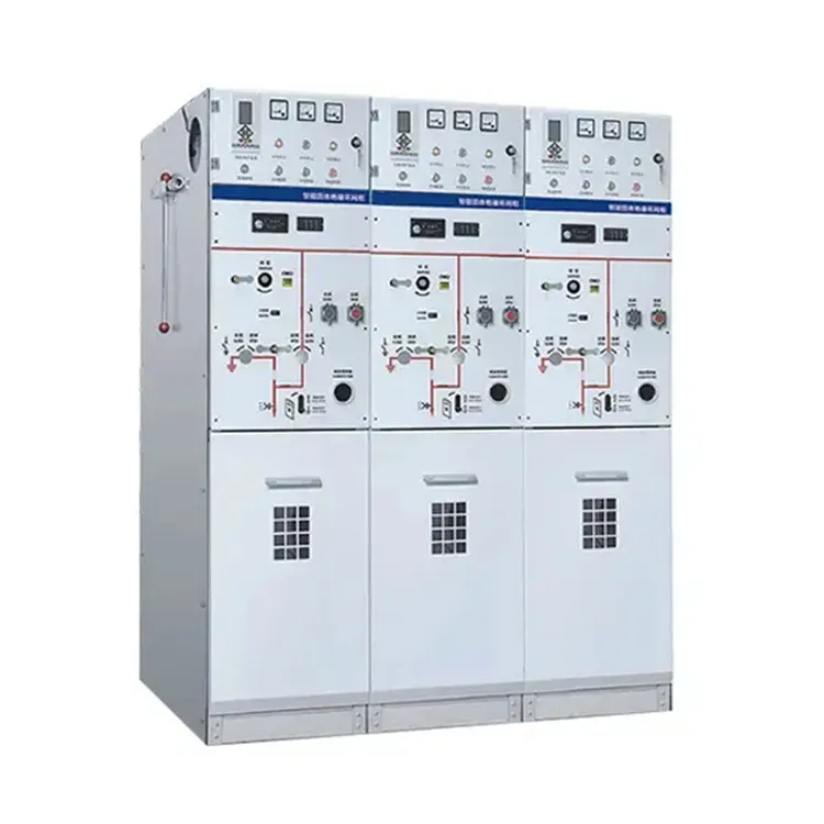
Ring feeders lose selectivity when procurement teams buy an RMU shell without locking the protection philosophy. Upstream breakers, local fuse-switch combinations, and downstream transformer fuses must clear faults in sequence so only the affected section opens.
For ring main unit protection, the purchase order should reference measurable coordination inputs—maximum three-phase and earth-fault currents, fuse curves or breaker interrupting ratings, CT ratios, and required setting sheets—rather than catalog adjectives alone.
Cross-check public information on Shenheng Power and confirm final limits with your utility or consulting protection engineer. Related buying context appears in the Ring Main Unit Selection Guide.
Lock these inputs before normalizing bids:
| Input | Why it matters | Typical source |
|---|---|---|
| Feeder topology and open points | Defines ring vs radial clearing paths | Approved single-line diagram |
| Max three-phase / earth-fault levels | Sets fuse or breaker duty | Fault study |
| Fuse-switch vs circuit-breaker scheme | Selects time-current family | Utility standard / EPC design |
| CT / VT ratios and burdens | Enables relay setting and metering | Protection schedule |
| Relay functions and setting ranges | Overcurrent, earth fault, interlocking | Setting philosophy document |
| Cable type and length | Affects loop impedance and reach | Cable schedule |
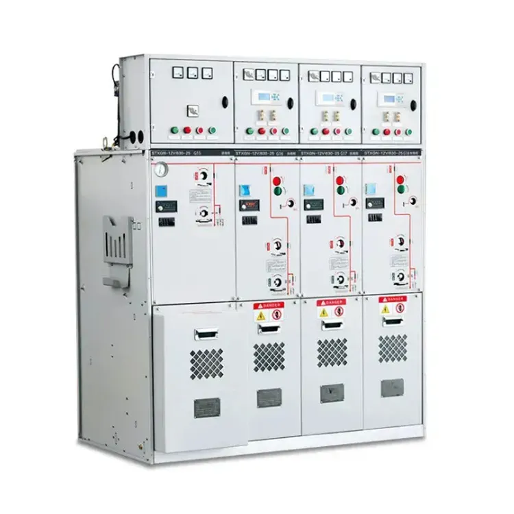
Request fuse time-current curves, breaker trip unit data, and outline drawings early so protection, civil, and commissioning teams can work in parallel.
Operating context changes acceptable coordination. Compact urban cable rings often favor fuse-switch tee-offs for simplicity, while industrial plants with motor inrush or higher short-circuit levels may require circuit-breaker modules and adjustable relays.
Earth-fault philosophy must match the system grounding method. Solidly grounded, resistance-grounded, and isolated systems do not share the same residual-current settings; state the grounding method in every RFQ.
Compare ring main unit scopes against traditional metal-clad panels when feeder counts, interlocking depth, or future expansion make a conventional lineup more practical—see RMU vs Traditional Switchgear.
Altitude, ambient temperature, and enclosure rating still affect thermal and dielectric margins. Record them even when the discussion centers on relays and fuses.
| Document / item | Purpose | When to request |
|---|---|---|
| Fault study summary | Confirms clearing duties | Before purchase order |
| Time-current coordination plot | Shows selectivity margins | Design review |
| CT / VT datasheets and ratios | Supports relay calculations | Design phase |
| Fuse curves or breaker trip curves | Matches vendor hardware to study | Bid normalization |
| Wiring / single-line diagram | Termination and interlocking | Before shipment |
| Factory routine / type test reports | Verifies switchgear ratings | Before purchase order |
| Setting sheet template | Records as-left values | Commissioning |
| Spare fuse / trip unit list | Outage readiness | Contract negotiation |
Attach this table to RFQs so vendors return comparable protection packages.
Installation quality often determines whether coordination survives the first fault. Confirm CT polarity, secondary grounding, fuse ratings, and nameplate interrupting capacity against the approved design before energization.
Before energization, plan secondary injection or primary injection tests where the project requires them, functional interlocking checks, and a signed as-left setting record. Outdoor SF6 units also need gas-pressure and cable-compartment checks—see the SF6 Ring Main Unit Outdoor Installation Guide.
Maintenance access should preserve the ability to replace fuses, extract modules, and re-verify settings without rewriting the coordination study.
For many ring main unit protection applications on MV cable networks, Shenheng Power publishes a relevant catalog starting point at SF6 ring main unit RMU switchgear.
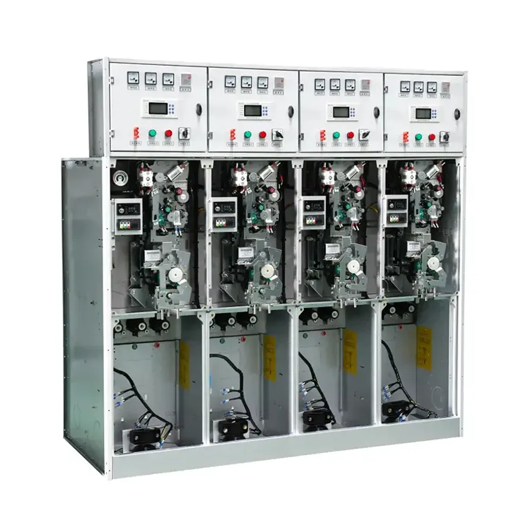
Fit boundary: This recommendation supports typical distribution and industrial RMU scopes documented on the product page. It is not a substitute for project-specific fault studies, relay setting calculations, or utility approval when unusual fault levels, grounding methods, or national grid-code rules apply.
If your study points to a different voltage class, fuse/breaker mix, or metal-clad lineup, review the broader medium voltage switchgear category and submit study inputs through Contact Shenheng Power.
Start with feeder topology, maximum three-phase and earth-fault currents, grounding method, fuse or breaker scheme, CT/VT ratios, and the utility or EPC setting philosophy.
Fuse-switch tee-offs rely on published fuse curves and fixed clearing times, while breaker modules allow adjustable relay curves. Both must still clear downstream faults before upstream devices operate.
List CT ratios and burdens, VT ratios if used, required protection functions, setting ranges, and whether secondary-injection test points are required at handover.
Sequence them so the nearest device clears first, with documented time or current margins to upstream sections. Exact values belong to the project study—not a catalog default.
Request test reports, GA drawings, wiring diagrams, fuse or trip curves, and a blank setting sheet aligned to the purchase order revision.
Before locking fuse ratings, relay curves, and interlocking that appear on the interconnection agreement or grid-code checklist.