Shenheng Power Equipment Co., Ltd.
- Home
- Products
Products
Since 2001, Shenheng Power has been a trusted manufacturer of power transmission and distribution equipment, delivering reliable electrical solutions globally.
- Solutions
- News & Blog
- Service
- About Us
- Contact Us
Since 2001, Shenheng Power has been a trusted manufacturer of power transmission and distribution equipment, delivering reliable electrical solutions globally.
MV switchgear shutter mechanism replacement requires an approved part and repair plan for the exact panel and withdrawable-device arrangement. The shutter, its operating linkage, mounting interfaces and associated interlocks form a safety-related system. A part that fits the available space is not necessarily compatible with the panel’s intended operating sequence or protective barriers. Identify the assembly and drawing revision, obtain manufacturer confirmation, investigate the original damage and agree the functional acceptance before any replacement work begins.
This guide concerns spare approval and maintenance planning. It gives no bypass method, racking sequence, manual shutter-opening technique or live-work instruction. Access and testing must follow the installation’s authorized procedure with qualified personnel.
A withdrawable switchgear assembly may use shutters to cover particular primary contact openings when the associated device is in a defined position. The actual arrangement differs by design. Obtain the panel manual and sectional drawings rather than assuming every shutter behaves like one shown in a training video.
Identify the protected openings, the intended shutter states and the device that operates the mechanism. Confirm whether different shutters or linkages serve different contact groups. The manufacturer’s documentation should explain the approved relationships without the maintenance team having to infer them from a damaged mechanism.
For a medium voltage switchgear panel, request the shutter spare against the specific unit and revision. An external cabinet photograph cannot establish the internal barrier arrangement, operating linkage or compatibility of a replacement component. Do not assume interchangeability across an entire product-family name.
Record the panel serial number, cubicle designation and relevant drawing references. Include the associated breaker or other withdrawable-device identity where it forms part of the mechanism interface. A replacement reviewed against only the cubicle may miss a mismatch introduced by a different truck, revision or adapter.
Describe the condition that prompted replacement: broken or bent linkage, incomplete movement, damaged barrier, loose mounting or another observed problem. Preserve photographs and maintenance history. Keep the description factual; a jammed mechanism does not by itself prove whether the cause is wear, misalignment or an unsuitable component.
The HSE switchgear safety guidance provides management context for selection, operation and maintenance of high-voltage switchgear. It does not approve a particular shutter spare or provide the panel-specific operating sequence. That information must come from the actual equipment documentation.
Ask the manufacturer which components must be supplied and checked together. A single replacement plate may be inappropriate if a linkage, support or guide is also damaged. The spare package should identify included items, retained components and any associated adjustments or inspection requirements.
If a revised component is offered, request its applicability and any required companion changes. Keep the approved revision in the work order. Avoid mixing old and new parts merely because their fixing holes appear similar.
| Interface | Evidence required for review | Concern that needs resolution |
|---|---|---|
| Panel applicability | Serial number and controlled drawing | Spare selected by cabinet appearance |
| Device interface | Associated truck or breaker reference | Mechanism operates differently with another device |
| Barrier geometry | Approved shutter and opening arrangement | Incomplete intended coverage |
| Operating linkage | Defined kit and retained parts | A new plate leaves damaged actuation in place |
| Mounting and guides | Condition and approved repair detail | Distortion or misalignment remains |
| Interlocks | Functional requirements for the actual assembly | Repair changes intended operating relationships |
| Acceptance | Manufacturer-supported test scope and criteria | No evidence of complete safe function |
This is an approval checklist, not an operating procedure. It contains no instructions for defeating barriers or reaching primary contacts.
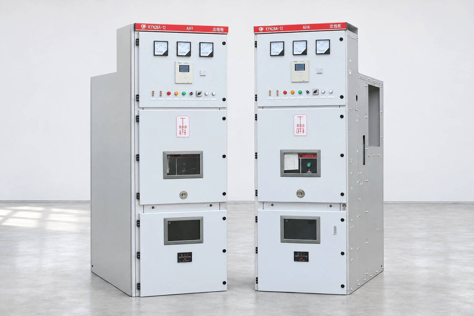
A failure may involve more than the visibly damaged part. The responsible engineer should define whether the inspection includes supports, guides, mechanism alignment, the withdrawable device and any evidence of inappropriate operation. Do not continue operating a stiff or damaged mechanism simply to gather more observations.
Review the maintenance history and any recent change to the associated device. Note whether the problem appeared after a repair, replacement or transport event. That sequence can help the manufacturer assess the cause without encouraging an unsupported diagnosis from a single photograph.
The fixed and withdrawable switchgear comparison explains the broader arrangement. The earthing switch interlock guide addresses another related safety interface. Keep those topics connected, but do not assume that restoring one interlock proves that the shutter system is also satisfactory.
Do not grind, bend, drill or add spacers to an unapproved shutter component to make it move. A modification can change alignment, barrier coverage, mechanical strength or the relationship with an interlock. If the supplied part does not fit as documented, stop for manufacturer review.
A repair proposal should describe any change from the original arrangement and the engineering basis for accepting it. If the original part is unavailable, ask for a documented replacement strategy rather than an informal instruction to adapt whatever is in stock.
An obsolete assembly may require a broader engineered solution. That decision should remain visible in the approval and asset records. Calling a modification a “like-for-like spare” does not make it one, and may deprive the next maintenance team of information it needs.
Shutter work can involve barriers close to primary electrical circuits. Define isolation, backfeed risks, stored energy, adjacent equipment and supervision through the site’s formal process. The HSE guidance on electrical work explains general planning and competence principles. It is not an authorization to open a shutter or enter a compartment.
Ask the manufacturer what safe test arrangement is needed after replacement. The functional checks should be planned so personnel do not have to improvise access or defeat a protective feature. Identify who controls the equipment and who may authorize each stage.
If the intended test cannot be completed under the approved conditions, record the limitation and obtain an engineering decision. A partial check should not be reported as a complete verification merely because the outage window is ending.
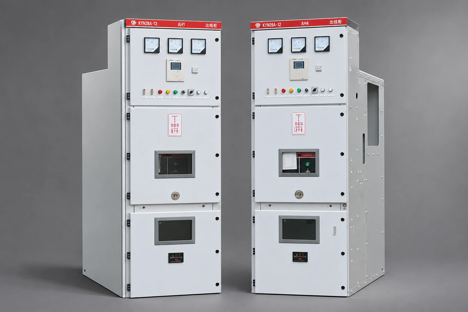
The acceptance package should identify the intended shutter states, movement, coverage and associated interlock relationships for the actual design. It should also address the components disturbed during the repair. The manufacturer or responsible engineer must supply the applicable criteria and authorized test method.
A visual observation that a plate moves is not sufficient by itself. The review needs to establish that the mechanism performs its intended function in the approved assembly, using the correct associated device and without leaving unresolved damage or interference.
Retain the results with the work order, including the installed part revision and any deviations. If the repair changes drawings, update them before handover. Future staff should not have to rediscover a site modification by opening the panel.
Provide the same panel identification, observed condition and requested scope to each qualified supplier. Ask whether the quotation covers only parts, a complete mechanism kit, engineering applicability review, installation support or acceptance testing. State who is responsible for the associated device and any further damage discovered during the outage.
Request a clear list of exclusions. A cheaper quotation may omit the review of a damaged mounting or require the owner to provide the test arrangement. Those differences matter more than the price of an individual shutter plate.
Use the medium voltage switchgear overview for broader procurement context. The site acceptance checklist can help organize records, but the actual post-repair test package must remain specific to the mechanism, panel and work performed. A generic checklist cannot approve a substitute safety component.
The following US Department of Labor video introduces hazardous energy control. It is relevant background for planning work on an electrical assembly and its stored-energy mechanisms. It does not show shutter replacement, authorize manual shutter access or replace the switchgear-specific isolation and test procedures.
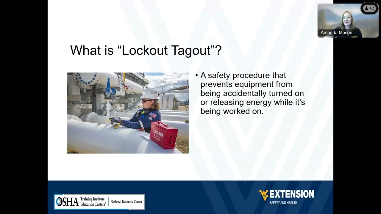
Further learning: Stand Up For Safety and Health – Lockout tagout — USDepartmentofLabor. Open on YouTube.
Only with documented approval for the actual assembly and associated device. Similar appearance and matching holes do not establish barrier coverage, movement or interlock compatibility. Supply both identities and obtain the approved replacement scope before installation.
Not necessarily. Linkages, guides, mountings or the associated device may also need investigation. The responsible engineer should define the repair boundary based on the observed condition and manufacturer guidance. Do not leave a damaged actuation component behind an apparently new barrier.
Adjustment must follow the approved equipment instructions under safe conditions. Do not force, modify or bypass a mechanism to make an unsuitable spare work. Unexplained stiffness or interference requires investigation before the assembly is accepted.
Record the panel and associated device, approved spare revision, work performed, inspection and functional results, and acceptance authority. Preserve any drawing changes or limitations. The record should demonstrate which intended functions were verified and identify anything still unresolved.