Shenheng Power Equipment Co., Ltd.
- Home
- Products
Products
Since 2001, Shenheng Power has been a trusted manufacturer of power transmission and distribution equipment, delivering reliable electrical solutions globally.
- Solutions
- News & Blog
- Service
- About Us
- Contact Us
Since 2001, Shenheng Power has been a trusted manufacturer of power transmission and distribution equipment, delivering reliable electrical solutions globally.
Low voltage switchgear replacement circuit breaker compatibility must be established for the complete assembly and its intended duty. Matching current rating, mounting dimensions or the manufacturer’s name is insufficient. A replacement can affect heat dissipation, short-circuit performance, connections, protection coordination and auxiliary functions. Before purchase, identify the existing assembly and device, obtain a documented substitution assessment, and agree the inspection and testing needed before return to service. This guide organizes the buyer’s evidence and approval process; it does not provide instructions for live work, device installation or changes to protection settings.
Related background: Low Voltage Switchgear Protection: A Practical Strategy
Start with the switchboard identification, original drawings and actual installed configuration. A device label provides only part of the information. The assembly may have been modified since delivery, and the manufacturer’s original configuration may differ from what is present today. Record the serial number, cubicle or feeder designation, original device reference and known modifications.
Distinguish the assembly manufacturer from the manufacturer of its components. The company supplying the breaker may not hold the design records for the complete cabinet. Ask who can evaluate the proposed substitution within that assembly and who accepts responsibility for any resulting changes.
The GAMBICA guidance on modification and maintenance of installed assemblies specifically addresses low-voltage assemblies. It emphasizes the technical knowledge needed for such work. Use that context to appoint competent reviewers rather than leaving compatibility to a purchasing comparison of catalogue entries.
An exact replacement still needs identity and condition checks. Confirm the complete reference, poles, accessories, control supply, trip unit, terminal arrangement and relevant revisions. A supplier description such as “same series” may conceal options that matter to the application. Record exactly what is being supplied.
A different series, successor model or alternative brand requires a broader assessment. Even when the supplier calls it a direct replacement, ask what that claim covers. It may describe physical mounting rather than the assembly’s thermal performance, fault withstand or control functions. Obtain the relevant declaration and its scope in writing.
Treat a retrofit kit as an engineered change with its own documentation. Identify every changed item, drawing revision and required inspection. A kit does not become acceptable merely because it can be installed without machining the enclosure. Conversely, the need for assessment does not mean every substitution requires the same tests: the responsible specialist must establish the applicable verification route.
Review the system voltage, frequency, load duty and fault conditions against the proposed device and the assembly. Compare the relevant ratings using their full definitions and applicable conditions. An isolated breaking-capacity figure is not a complete statement of compatibility with an existing switchboard.
Protection must also be considered as a system. A replacement trip unit may offer different characteristics, adjustment ranges or functions. The settings from the removed device should not be copied mechanically into a different platform. The protection specialist needs to check the actual load, downstream equipment, upstream devices and the required discrimination or coordination objectives.
Where a proposal changes current-limiting behavior, assess the consequences for the assembly and protected components. Ask the reviewer to identify the relevant evidence and limitations. Do not infer that a higher catalogue rating automatically provides equivalent performance in every respect or that it preserves all original design verification assumptions.
Device losses, connection arrangements and the surrounding enclosure interact. A replacement that fits the space may have different heat dissipation or terminal requirements. Compare the proposed arrangement with the basis used to establish the assembly’s performance, including any restrictions on orientation, ventilation or adjacent components.
The BEAMA guide to verification other than by test illustrates the relevance of device losses, terminal temperature rise, physical arrangement and short-circuit characteristics. Its examples are conditional verification exercises, not permission to substitute an arbitrary breaker using a single comparison.
Record changes to conductors, terminals, supports or mounting. An adapter can introduce new interfaces that need review even if the device itself has familiar ratings. Evaluate the complete proposed arrangement, including required clearances and manufacturer instructions, rather than approving the breaker first and treating the connections as a later installation detail.
Use the table below to organize a request for assessment. It deliberately avoids universal numerical criteria. The applicable standard, original verification records, actual assembly and proposed change determine what evidence is necessary.
| Review area | Evidence to request | Approval question |
|---|---|---|
| Equipment identity | Assembly and device references, revisions, modification history | Are the reviewed records the installed configuration? |
| Electrical duty | System conditions, load and fault information | Is the proposed device suitable for the actual duty? |
| Thermal performance | Losses, connections, enclosure arrangement and verification basis | Does the change remain within accepted conditions? |
| Fault performance | Relevant characteristics and assembly assessment | Are the original assumptions preserved or reassessed? |
| Functional interfaces | Control schematics, accessories, interlocks and indications | Will every required function operate as intended? |
| Return to service | Approved inspection, testing and settings records | Is there documented authority to release the assembly? |
The BEAMA assembly verification guide explains the broader distinction between design and routine verification. Use the edition and national requirements applicable to the project; a routine functional check alone does not establish every design characteristic affected by substitution.
A breaker can have the correct main-circuit duty while its auxiliaries remain unsuitable. Check control supply, closing and tripping functions, auxiliary contacts, position indication and any interfaces used by automatic transfer, process control or monitoring systems. Match functions and interfaces, not just the number of wires visible in a photograph.
For withdrawable equipment, assess the moving and fixed portions together. Confirm compatibility of the cradle, primary connections, secondary connections, position-related functions and the approved mechanical arrangement. A unit that appears to rack into place has not thereby demonstrated correct operation under all intended conditions.
Keep changes visible in the drawings. If an accessory is omitted, a signal changes meaning or a control scheme is revised, update the relevant documentation and operating instructions. Hidden workarounds can leave the next maintenance team with a drawing that no longer describes the installed system.
A replacement request is also an opportunity to check whether the surrounding assembly remains suitable for continued service. Document visible deterioration and previous modifications before deciding that replacing one component resolves the problem. The assessment may identify issues with connections, supports or control circuits that the new breaker cannot address.
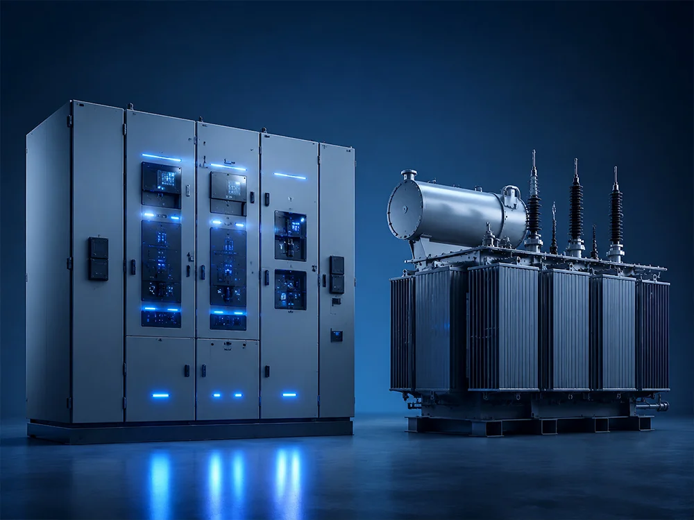
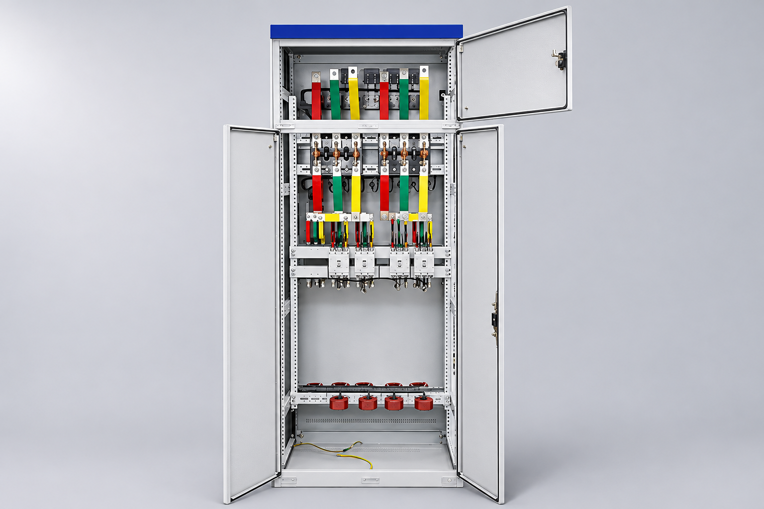
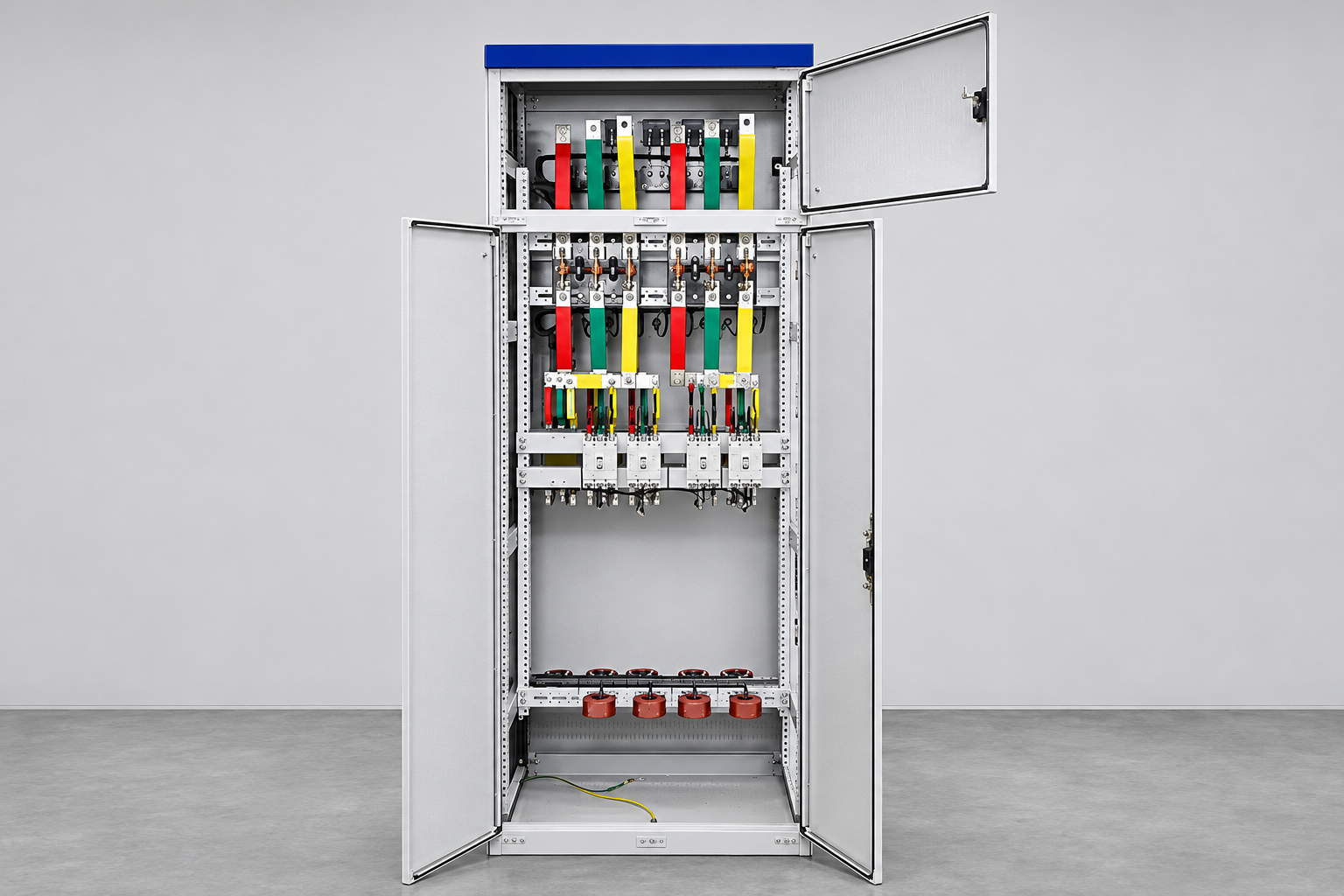
For procurement context, review Shenheng low voltage switchgear together with the project’s feeder schedule and assembly requirements. The product reference illustration in this article shows a low-voltage cabinet family; it is not evidence that any particular breaker fits that cabinet or that an existing site unit has been evaluated.
The IEC 61439 assembly guide provides the broader framework, while LV panel feeder protection concerns protection selection. This article addresses the narrower decision of whether a proposed spare or replacement can be accepted in an identified assembly. Keep those decisions connected without treating them as interchangeable approvals.
Agree the assessment and return-to-service plan before ordering, wherever possible. State the documents required at delivery, checks before installation, inspection after work, functional tests and protection evidence. Name the people authorized to accept each stage and identify the conditions that would stop the work.
Arrange a fallback for an unacceptable or incomplete delivery. An outage deadline should not determine the technical conclusion. If the supplier cannot provide evidence for the proposed configuration, retain the unresolved item and consider an approved alternative, an engineered retrofit or a wider replacement scope.
For the physical maintenance context, see withdrawable LV switchgear service access. Safe access is necessary for competent work, but sufficient working room does not prove device compatibility. Likewise, a successful no-load operation does not establish thermal or short-circuit performance.
Suppose an industrial plant requests a spare and the original model is unavailable. A distributor proposes a newer breaker with the same nominal current and similar dimensions. The purchasing team should first obtain the exact references and identify whether the offer is an identical spare, a documented manufacturer substitution or an independent retrofit proposal.
The review then compares electrical duty, thermal interfaces, connections, protection and controls. If the new trip unit needs revised coordination or the mounting changes conductor geometry, those effects belong in the assessment before purchase approval. None of these hypothetical conditions proves the proposal is unacceptable; they identify what must be resolved.
The final record should state the accepted configuration, evidence, limitations and verification completed. Keep the old and new device identities, revised drawings and settings in the maintenance file. That record makes a later spare order more reliable and prevents an approved one-off substitution from turning into an undocumented assumption about every cubicle.
This educational overview explains the IEC 61439 assembly framework relevant to a device-substitution review. It does not certify a replacement or replace the applicable verification assessment.
Further learning: Overview of IEC 61439-1 and IEC 61439-2 — Electrical Engineering Knowledge Sharing. Open the video on YouTube.
No. Evaluate the complete duty, assembly interfaces, thermal and fault performance, protection functions and controls. The current rating is only one input to the compatibility assessment.
No. Different series, revisions and accessory combinations can matter. Obtain the manufacturer’s applicable substitution information and an assessment for the identified assembly.
No. Fit does not establish heat dissipation, fault performance, connection suitability or functional behavior. The approved review must address the complete arrangement.
Keep device and assembly identities, the substitution assessment, accepted limitations, revised drawings, settings records, inspection and test results, and the return-to-service authorization.