Shenheng Power Equipment Co., Ltd.
- Home
- Products
Products
Since 2001, Shenheng Power has been a trusted manufacturer of power transmission and distribution equipment, delivering reliable electrical solutions globally.
- Solutions
- News & Blog
- Service
- About Us
- Contact Us
Since 2001, Shenheng Power has been a trusted manufacturer of power transmission and distribution equipment, delivering reliable electrical solutions globally.
The main difference in an autotransformer vs two winding transformer comparison is the electrical connection between the input and output circuits. An autotransformer uses a common winding portion and therefore does not provide galvanic separation between those circuits. A conventional two-winding transformer transfers power magnetically between electrically separate windings. The autotransformer arrangement can offer material and size advantages, especially when the voltage ratio is close, but that benefit must be evaluated alongside isolation, grounding, fault duty and protection requirements. The correct purchase starts with the system requirement, rather than a promise of lower transformer cost.
An autotransformer has series and common winding portions in the relevant connection. Part of the power transfer involves the electrical connection between circuits, while another part involves transformer action. A conventional two-winding arrangement uses separate input and output windings coupled through the magnetic core. This difference defines what the system designer must consider.
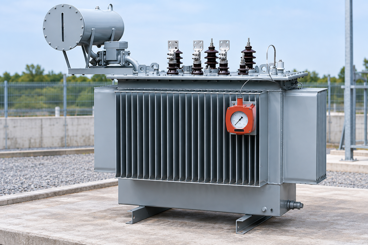
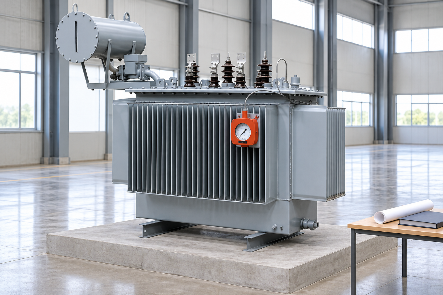
External appearance is not a reliable way to distinguish them. Both may be enclosed in an oil-filled tank, and the visible bushings or cooling arrangement do not reveal the complete winding connections. Read the approved connection diagram, terminal schedule and nameplate information. Do not identify winding topology from a product photograph or from the word power transformer alone.
NPTEL’s Electrical Machines I course includes dedicated teaching on autotransformers and comparison with two-winding transformers. Use the underlying principles to frame the enquiry, then obtain the actual manufacturer’s configuration and guaranteed performance. A course example cannot establish the ratings or suitability of a proposed commercial unit.
If the project needs electrical separation between the supply and load circuits, an autotransformer connection does not provide that separation. Decide this requirement early because it can eliminate the topology before cost comparison begins. A lower output voltage does not automatically mean the load circuit is electrically separated from the supply.
A two-winding transformer provides separation between its windings, but the installed grounding and bonding scheme still matters. External connections can create conductive paths elsewhere in the system. The transformer alone does not guarantee that an installation is safe to touch, free from noise or compliant with every protective measure required by local rules.
The transformer neutral-grounding guide addresses one important system interface. Ask the designer to identify the grounding arrangement, neutral requirements and protection responsibilities for the chosen topology. Do not select equipment first and leave those decisions to site wiring changes after delivery.
| Decision point | Autotransformer | Conventional two-winding transformer |
|---|---|---|
| Input-output connection | Common electrical connection is part of the topology | Separate windings provide galvanic separation at the transformer |
| Close voltage ratios | Can offer a material advantage worth evaluating | May require a larger magnetic transfer duty for the same throughput |
| Grounding interface | Must suit the electrically connected system arrangement | Winding connection can provide a separate system interface, subject to design |
| Fault study | Requires the proposed impedance and connection data | Also requires configuration-specific impedance and connection data |
| Procurement evidence | Diagram must identify common and series portions and terminal duties | Diagram must identify separate winding duties and connection group |
| Selection limit | Unsuitable where the required input-output separation cannot be achieved | Appropriate separation still needs insulation, grounding and protection review |
The table describes connection principles rather than guaranteed commercial performance. Compare actual offers at the same rating, cooling duty, environmental conditions, loss evaluation basis and required accessories. Neither topology is automatically better for every industrial project.
The IGNOU transformer learning unit discusses the common-connected arrangement and its limitations. For an ideal step-down autotransformer, let k equal the lower voltage divided by the higher voltage. A useful conceptual relationship is that the portion of throughput transferred by transformer action is (1 − k) times the total apparent power. As the two voltages become closer, that fraction becomes smaller. This explains the potential material advantage without promising a particular price or physical size.
For a hypothetical 100 kVA ideal arrangement between 500 V and 400 V, k equals 0.8. The conceptual transformed portion is therefore 20 kVA. The remaining power transfer is associated with the conductive connection. These values illustrate the principle only; they are not a winding design, insulation specification, conversion instruction or nameplate rating for an actual product.
Do not buy a transformer by applying that ideal relationship to a spare unit without engineering review. Real winding currents, thermal limits, insulation duties, fault stresses and terminal arrangements must be evaluated for the intended connection. The transformer sizing guide addresses the separate task of establishing the load requirement before a supplier selects the equipment.
State the normal input range, required output range, frequency and load characteristics. Identify whether the source and load grounding arrangements can remain electrically connected. Where the project requires a different neutral treatment or system reference, ask the designer how the proposed transformer connection provides it. The answer must come from the actual diagram.
Also identify operating changes. Parallel supplies, alternative sources or future expansion may alter the system assumptions behind the original selection. A topology acceptable in one operating mode should not be assumed suitable in every contingency. Keep those modes in the study and make the supplier aware of the ones relevant to its offer.
Do not confuse an adjustable autotransformer used in a laboratory with a utility or industrial power autotransformer. Both involve the common-connection principle, but their construction, duty and protection can differ substantially. Likewise, a motor-starting autotransformer has a defined starting function that should not be substituted for a continuous-duty power transformer without explicit engineering approval.
A topology label does not determine the available fault current at the load. The study needs the actual proposed impedance, source data, network arrangement and relevant operating conditions. Any claimed low-impedance advantage must be assessed alongside the interrupting and withstand duties it may create elsewhere in the system.
Use the transformer impedance and parallel-operation guide for the broader relationship. Request the definition, base and tolerance associated with the supplied impedance data. Comparing percentages without consistent bases can produce a misleading conclusion even when the numbers look similar.
Then coordinate protection with the selected winding arrangement. The responsible engineer should review the faults, measurement locations and clearing requirements relevant to that connection. A protection scheme copied from a conventional two-winding unit may need a different assessment when the circuits are electrically connected. This article deliberately avoids relay settings or wiring instructions because those depend on the project.
An autotransformer can have an efficiency advantage in suitable applications, but the actual comparison requires guaranteed no-load and load-loss information under stated conditions. Ask both bidders to use the same rating, reference conditions, cooling state and evaluation method. Do not turn a general topology benefit into an unsupported percentage saving.
Consider the load profile as well as full-load performance. A unit operating lightly for long periods may have a different economic balance from one carrying a steady high load. Use the owner’s agreed energy and loss-evaluation assumptions, and keep sensitivity to those assumptions visible. Acquisition price is only one part of the comparison.
Include installation, protection changes, spare strategy and maintenance access in the commercial review. A smaller transformer can still create additional system work. Conversely, a more expensive unit may simplify an interface the project must provide anyway. Compare the complete accepted solution rather than treating the quoted equipment price as the total project cost.
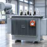
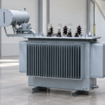
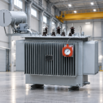
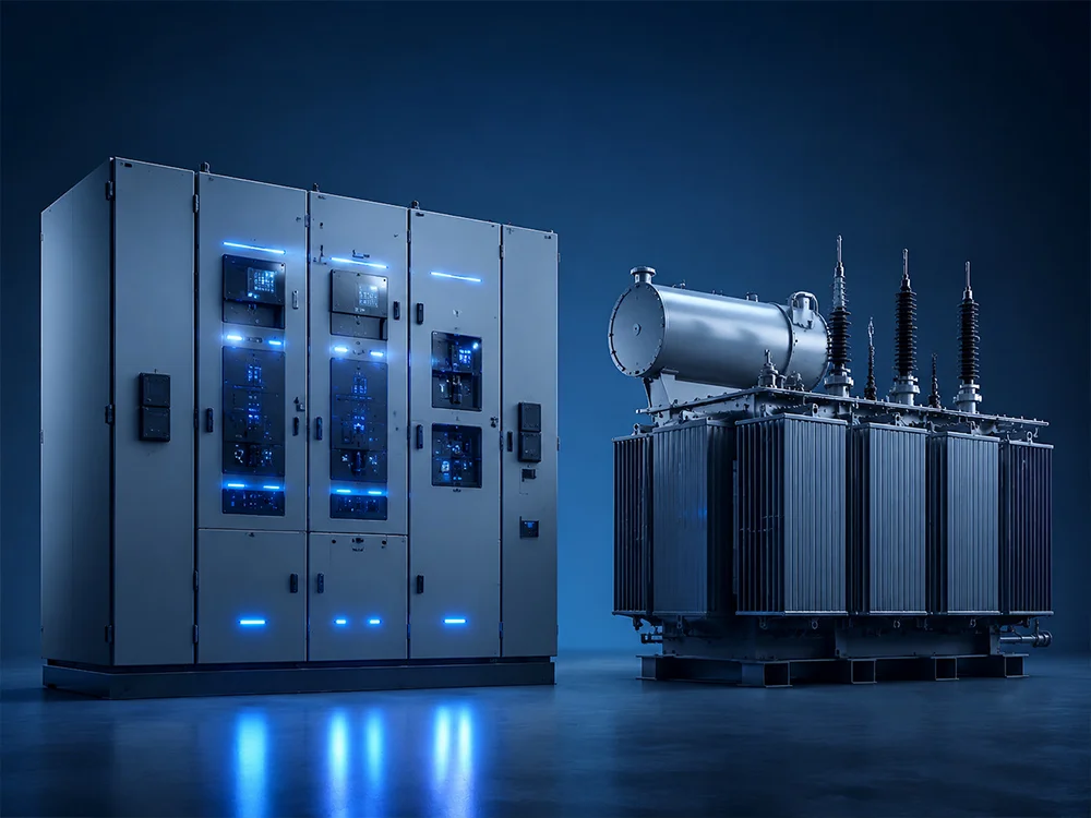
Shenheng’s oil-immersed industrial transformer page is a starting point for a project enquiry. The reference-based images in this article illustrate that equipment family only. They do not identify the photographed unit as an autotransformer or establish a particular winding configuration, loss guarantee or test certificate.
Provide the supplier with the single-line diagram and explicitly state whether an autotransformer or electrically separate two-winding arrangement is required. Ask it to return a winding and terminal diagram, guaranteed schedule, applicable standard, insulation requirements, impedance, cooling information and test proposal. Require deviations to be identified rather than hidden behind a generic catalog model.
NPTEL’s Electrical Machines I material from IIT Madras places autotransformers alongside transformer construction, testing and operating topics. That educational context reinforces a useful procurement principle: connection type is one part of the equipment and system review, not a replacement for the rest of the specification.
First decide whether input-output galvanic separation is required. If it is, exclude a proposed autotransformer connection from that requirement unless the system design is formally changed and approved. A purchasing team should not relax the isolation requirement simply because an alternative quote is cheaper.
Next establish the voltage ratio, load duty and grounding interfaces. If a common-connected topology is acceptable, ask for a genuine comparison at the same service conditions. Review impedance and protection consequences before accepting material or efficiency advantages. This prevents an attractive transformer offer from shifting unresolved cost or risk to the switchgear package.
Finally compare the accepted technical offers commercially and retain the decision record. List the assumptions that would require a new review, such as a changed source, parallel operating mode or revised load. At handover, verify that the delivered diagram and nameplate match the approved arrangement. This sequence turns a broad comparison into a decision that later teams can understand.
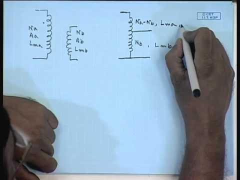
Further learning: Mod-01 Lec-17 Lecture-17-Auto Transformers — nptelhrd. Educational background; this is not an operating authorization. Open the video on YouTube.
The university lecture explains autotransformer fundamentals. It provides background for understanding the shared winding arrangement, but it does not authorize converting installed equipment, changing terminal connections or energizing a project without approved drawings and procedures.
No. Its input and output circuits share an electrical connection. Where the project requires separation at the transformer, specify and verify an appropriate separate-winding arrangement together with the complete grounding and protection design.
No universal saving can be promised. Close voltage ratios can offer a material advantage, but actual size, cost and losses depend on the rating, construction and service requirements. Compare guaranteed proposals on the same basis.
No. An exterior photograph cannot establish the internal connection. Confirm the topology using the approved winding diagram, terminal schedule, nameplate and project-specific manufacturer documentation.
Provide the voltage ratio, load duty, isolation requirement, grounding arrangement, operating modes and fault-study inputs. Review the proposed impedance, losses, protection interfaces and acceptance evidence before making the commercial selection.