
 Shenheng Power Equipment Co., Ltd.
- Home
- Products
Products
Since 2001, Shenheng Power has been a trusted manufacturer of power transmission and distribution equipment, delivering reliable electrical solutions globally.

- Solutions
- News & Blog
- Service
- About Us
- Contact Us
Since 2001, Shenheng Power has been a trusted manufacturer of power transmission and distribution equipment, delivering reliable electrical solutions globally.
Project engineers laying out 12kV metal clad switchgear need more than a catalog cubicle count — cable entry, busbar rating, arc boundaries, and relay interfaces must fit the approved single-line and room geometry.
This 12kv metal clad switchgear guide focuses on practical procurement and layout controls for the package below. Pair the checklist with the approved single-line for 12kv-metal-clad-switchgear-layout-checklist — it does not replace utility or consultant sign-off.
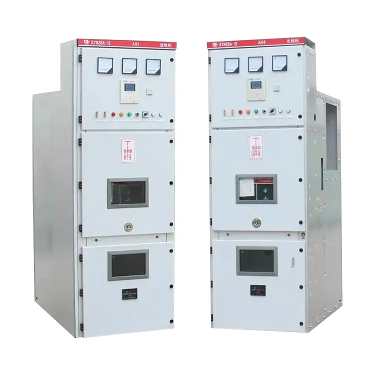
Metal clad boards define aisle widths, pressure relief paths, and maintenance access for decades. Changing cable entry after manufacture often forces civil and protection rework.
Treat the layout checklist as a design control document: every revision must reconcile feeder names, CT ratios, and interlocking notes with the latest single-line revision.
Related reading: metal clad switchgear arc mitigation overview and KYN28 switchgear interlock verification.
| Layout input | Failure mode if omitted | Owner |
|---|---|---|
| Rated voltage / insulation level | Wrong clearance class | Single-line diagram |
| Main busbar continuous rating | Thermal overload on future feeders | Load schedule |
| Short-time withstand | Busbar bracing inadequacy | Fault study |
| Cable entry (rear / bottom / side) | Civil trench mismatch | Cable design |
| Arc classification / relief path | Unsafe personnel aisle | Protection / safety |
| CT/VT and relay interface list | Protection settings delay | Relay engineer |
| Interlock and earthing switch notes | Unsafe racking sequences | Ops / manufacturer |
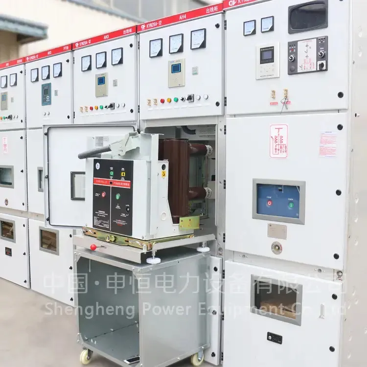
Important: For 12kv metal clad switchgear, freeze these inputs on a controlled revision before normalizing commercial bids; late changes cascade into civil, protection, and factory drawings — align with IEC standards practice and the project authority source notes.
Confirm front and rear aisle widths, door swing, and lifting height before ordering. Bottom-entry designs need trench depth and bending radius that match MV cable specs.
Arc-mitigation ducts or relief flaps must terminate outdoors or into approved zones — never into occupied corridors without a documented study.
| Drawing / data pack | Purpose | Send with quote |
|---|---|---|
| Cubicle arrangement GA | Room and aisle fit | Yes — with revision |
| Single-line with CT/VT ratios | Protection coordination | Yes — locked revision |
| Cable entry and gland plate detail | Trench / tray interface | Yes — before manufacture |
| Interlock logic description | Safe racking sequence | Yes — ops review |
| Arc relief path sketch | Safety acceptance | Yes — when IAC claimed |
| FAT / routine test plan | Witness schedule | Yes — contract annex |
| Nameplate and relay setting sheet | Commissioning dossier | Yes — before shipment |
Attach this table to every RFQ revision so vendors return comparable technical packages instead of catalog excerpts.
Witness mechanical racking, interlock defeat attempts, and primary injection where the contract requires it. On site, verify earthing switches, shutter operation, and CT polarity before first energization.
File as-built GA revisions with the protection settings pack so future feeder additions start from evidence rather than memory.
For many 12kv metal clad switchgear scopes, begin engineering review with Shenheng Power’s KYN28-12 medium voltage switchgear system catalog entry documented on the product page.
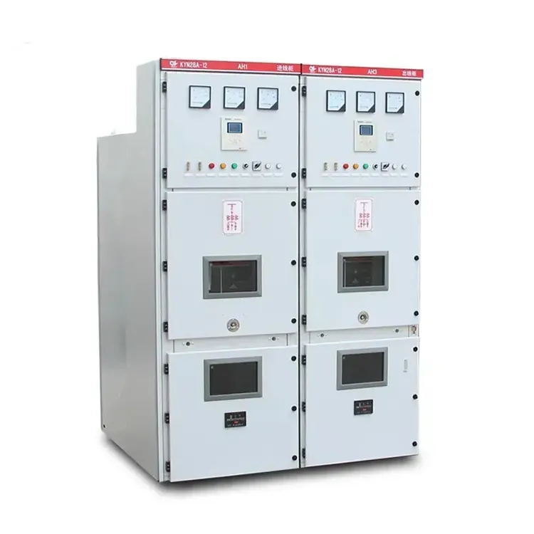
Application limits: For 12kv metal clad switchgear (12kv-metal-clad-switchgear-layout-checklist), treat the linked catalog page as an engineering starting point only. Do not freeze 12kv metal clad switchgear procurement when the project fault study, altitude derating, or utility type-approval envelope exceeds the published ratings on that product page.
If the 12kv metal clad switchgear study points to a different scheme or rating for 12kv-metal-clad-switchgear-layout-checklist, browse the category page and send study inputs through Contact Shenheng Power.
Front/rear aisle, door swing, lifting height, and arc relief termination must fit the architectural layout before PO.
Size the main bus for continuous and future feeder growth documented on the load schedule, not only today’s connected load.
When trench depth or bending radius cannot support bottom entry without violating cable manufacturer limits.
Relief path, classification claim, and any duct termination outside occupied zones should appear on the controlled GA.
CT/VT ratios, accuracy class, relay type, and wiring terminal maps so settings can be prepared in parallel with manufacture.
Agree the FAT list early — typically mechanical interlocking, dielectric checks, and functional racking demonstrations.






