Switchgear Earthing Switch Function and Interlocks
Release Time: 2026-10-02
A switchgear earthing switch connects a defined part of a circuit to earth as part of an approved isolation and access arrangement. Its interlocks help prevent incompatible switching states, such as attempting a normal closing operation while the associated earthing switch is closed. However, interlocks do not prove that equipment is de-energized and do not replace lockout, voltage verification or the authorized switching procedure. Selection must identify exactly what is earthed, the switch duty, the possible sources of backfeed and the mechanical and electrical permissives used by the complete assembly.
Identify the circuit section being earthed
Begin with the single-line diagram and the manufacturer’s functional drawing. Determine whether the earthing switch applies to the cable side, a bus section or another defined circuit section. The location of a handle on the front of a cabinet does not establish which conductors it connects to earth.
Review all possible supplies, including a second incoming feeder, transformer backfeed, embedded generation and test equipment. A cable connected to an open local breaker may remain energized from its far end. The switching plan must account for that possibility rather than assume that the local device controls every energy source.
استخدم substation single-line diagram guide to organize the circuit relationships. Then obtain the actual manufacturer’s diagram. Educational drawings help explain functions, but they cannot identify the safe boundary of a particular installed panel.
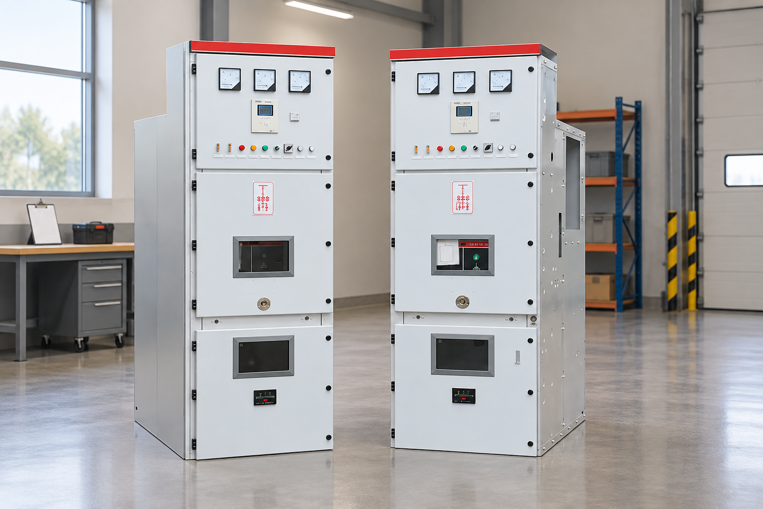
Review the actual interlock matrix and permitted operating states. Reference-based illustration.
Functions and evidence to check
عنصر
What it establishes
What it does not establish
Required evidence
Earthing switch position
Indicated state of a specified device
Absence of voltage from every source
Mechanical position and circuit drawing
Mechanical interlock
Prevention of defined incompatible operations
Complete isolation of a remote supply
Interlock sequence and functional test
Electrical permissive
Control logic allows or inhibits a command
A secure physical isolation boundary
Approved logic and failure-state assessment
Voltage indication
Information within the indicator’s stated capability
Automatic permission to enter a compartment
Device instructions and verification procedure
Earthing connection
Intended conductive connection to earth
Adequate temporary grounding for every task
Rated duty and site grounding assessment
Door or key arrangement
Controlled access under specified states
Safety after bypass, damage or incorrect assembly
Key schedule and access instructions
The table defines questions for the designer and owner. It is not a switching sequence. IEC 62271-200 provides the scope for applicable metal-enclosed assemblies; confirm the project edition and the particular equipment’s evidence.
Making duty and short-time duty are different
An earthing switch can have specified capabilities for closing onto an energized circuit and for carrying fault current for a specified duration. Those capabilities are distinct and must be selected against the actual network. A current figure without its duty, duration and test basis is incomplete.
A making capability is not an instruction to deliberately close onto a live circuit. It addresses a defined equipment duty and the consequences of an abnormal situation. Normal operation still follows the approved isolation and voltage-verification procedure. Procurement documents should distinguish rated capability from operating permission.
Ask the supplier for the earthing-switch ratings and the assembly configuration covered by the tests. Review the prospective fault duty and protection clearing time with the project engineer. Do not substitute a generic switch rating for evidence that the complete panel and its connections meet the installation requirements.
Mechanical interlocks should have a documented sequence
Describe every normal state and allowed transition. Examples may include breaker open or closed, withdrawable element service or test position, earthing switch open or closed, and accessible compartments. The exact arrangement varies by design, so the correct document is the offered equipment’s interlock matrix.
A useful matrix states the starting condition, attempted operation, expected permitted or blocked result and the means of verification. That format exposes gaps more effectively than a general statement that the equipment includes “five protections.” It also supports consistent factory and site testing.
Consider removal, adjustment and maintenance. If an interlock can be temporarily overridden by authorized personnel, the instructions must explain the controlled circumstances and restoration checks. An undocumented bypass should be treated as a defect requiring review. Operators should not force handles or defeat a mechanism because the expected operation is unavailable.
Electrical controls and failure behavior
Motorized mechanisms and remote operation can add electrical permissives to the physical interlocks. Check which signals are used, how their status is obtained and what happens when control power or communications fail. A permissive based on an incorrect indication can create an unsafe command even if the control screen looks reasonable.
Identify whether local and remote modes apply the same essential interlocks. Review selector positions, auxiliary contacts, timeout alarms and disagreement indications. If remote commands are permitted, the control scheme must prevent automatic retries from concealing a mechanical problem or repeatedly applying a blocked command.
ال motorized RMU guide explains related questions about remote control and operating feedback. These complement the earthing-switch assessment because control functionality and safe access must remain coordinated across every operating mode.
Interlocks cannot replace safe isolation
An open breaker, a locked control switch and a closed earthing switch are different elements of a safety arrangement. Each has a defined purpose. The approved procedure determines how isolation, prevention of reconnection, voltage verification and grounding are established for the particular work.
OSHA’s work-practice requirements explicitly distinguish control devices from isolation. This is a useful reference for recognizing why a push button, selector or interlock should not be treated as the sole means of de-energizing equipment. Applicable local electrical safety rules and the owner’s authorized program govern the actual task.
Where protective grounding is required, assess the relevant grounding arrangement and possible potential differences. The installed earthing switch does not automatically address every remote work location or every testing condition. Qualified personnel must evaluate the task boundary and any additional measures under the applicable procedure.
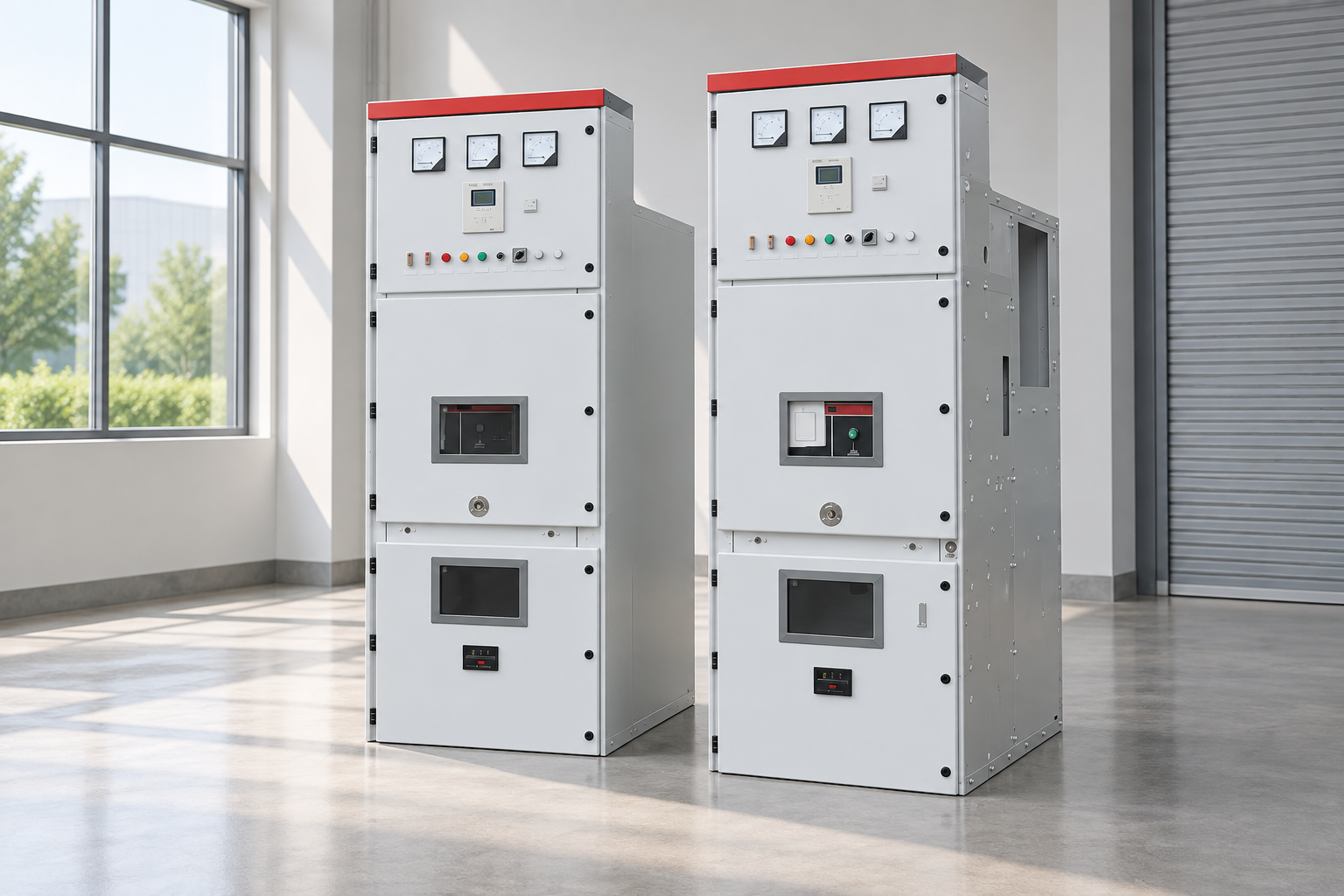
Test permitted and prohibited operations through an approved procedure. Reference-based illustration.
Commissioning an interlock arrangement
Before functional tests, match the equipment serial number, circuit designation, drawing revision and key schedule. Confirm that the tested assembly is in the approved safe state and that the test method cannot inadvertently energize conductors. Use the manufacturer’s procedure and the site commissioning program.
Test both allowed and blocked operations. A test that demonstrates only that a handle can move misses half of the interlock function. Record the actual starting state and result for each operation. Investigate unexpected movement, missing indication, abnormal force or an operation that remains permitted in a prohibited state.
For electrical controls, verify local and remote commands, loss of control supply, conflicting indications and reset behavior. Confirm alarm destinations and the response expected from operators. Retain the results with the RMU commissioning record or the corresponding switchgear acceptance package.
Common problems that require investigation
A handle that cannot move may indicate a valid interlock, incorrect operating sequence, incomplete device travel or a mechanical defect. The response should be to identify the condition, not increase force. Check the instructions and escalate unexplained behavior through the authorized maintenance process.
A position indication that disagrees with another signal can result from auxiliary-contact adjustment, wiring, mechanism travel or a damaged indicator. Do not choose the most convenient indication and continue. Establish the actual state through the approved verification method and correct the cause before returning the arrangement to normal service.
Loose keys, duplicated keys or an inaccurate key schedule can undermine a trapped-key system. Include key custody and identification in the operational controls. If a key arrangement has been modified, compare it with the current switching philosophy and obtain a formal review rather than preserving an undocumented field change.
Specify the complete panel interface
For an inquiry about KYN28-style medium-voltage switchgear, identify the required earthing location and assembly function. Do not infer the internal insulation technology or interlock details solely from a model name or product title; use the offered drawings and reports.
Provide rated voltage, source fault duty, clearing time, cable arrangement, access requirements and operating modes. Request earthing-switch duty, mechanical and electrical interlock matrices, indication details, key schedule and maintenance instructions. Identify whether any site-supplied equipment participates in the permissives.
During acceptance, require the supplier to list deviations and optional features. Confirm the final drawing revision after site changes. The equipment labels, control logic, keys and written procedure must describe the same arrangement. That agreement is more useful than a general compliance statement unsupported by the installed configuration.
Further learning
Further learning: Isolator And Earthing Switch – Requirement And Definition – Substation Equipment & Switching Devices — Ekeeda. This educational video supports the topic; it is not a product demonstration or an operating authorization. افتح الفيديو على يوتيوب.
الأسئلة الشائعة
Can an earthing switch safely close on a live cable?
Do not treat its rated making capability as operating permission. Normal use follows the approved isolation, verification and grounding procedure. Confirm the specific equipment duty and possible remote supplies.
Is an interlocked door enough to make a compartment safe?
No. It is one element of the equipment arrangement. Proper isolation and verification remain necessary, and bypassed, damaged or incorrectly adjusted interlocks require investigation.
Why does the earthing-switch handle refuse to move?
It may be correctly blocked by another device state, or a fault may be present. Follow the documented sequence and investigate unexpected behavior. Do not force the handle or remove the interlock.
What should commissioning prove?
It should prove both permitted and prohibited operations, indications, local and remote behavior, and defined failure responses. Record starting states and results against the actual drawings.

 شركة شنغهنغ لعدات الطاقة المحدودة.