Shenheng Power Equipment Co., Ltd.
- Home
- Products
Products
Since 2001, Shenheng Power has been a trusted manufacturer of power transmission and distribution equipment, delivering reliable electrical solutions globally.
- Solutions
- News & Blog
- Service
- About Us
- Contact Us
Since 2001, Shenheng Power has been a trusted manufacturer of power transmission and distribution equipment, delivering reliable electrical solutions globally.
Switchgear busbar bolt torque must come from the approved instructions for the specific joint, hardware and surface condition. A bolt-diameter chart cannot establish the correct setting for every copper or aluminum busbar connection. Reliable acceptance combines the right joint components, controlled surface preparation, suitable tools, the specified assembly sequence and traceable records. Electrical testing and later thermal inspection provide additional evidence; neither replaces correct assembly. This guide explains what to request and inspect without publishing a generic torque value that could damage an actual switchgear joint.
Two connections using the same bolt diameter can have different requirements. The busbar material, contact plating, number of conductors, overlap geometry, fastener grade, washer arrangement and thread condition all matter. A torque value copied from another panel may refer to different hardware or a different tightening method.
Begin with the switchgear model, panel reference and joint location. Determine whether the connection is factory assembled, a shipping split, an extension interface or a site cable termination. These categories can have separate instructions. A cable lug value should not silently become the setting for a busbar splice.
Request the approved drawing and installation instruction revision for the supplied assembly. If a label and a manual disagree, stop that joint’s assembly and obtain written clarification. Do not resolve a conflict by choosing the larger value, averaging two values or relying on an installer’s recollection of a similar project.
Tightening torque is used to create a clamping force, but it does not directly measure the contact pressure throughout a busbar interface. Friction at threads and bearing surfaces affects how much applied torque becomes bolt tension. Consequently, the same wrench reading can produce different joint conditions when the hardware or lubrication changes.
NASA’s Fastener Design Manual explains general fastening considerations, including finishes and lubricants. It is useful mechanical background, not a switchgear torque schedule. Its aerospace examples must not be transferred into electrical equipment as approved installation values.
Excessive tightening can damage threads, deform components or compromise the intended joint stack. Insufficient tightening can leave inadequate contact pressure. More torque is therefore not a universal remedy for a hot connection. Investigate the equipment condition and use the manufacturer’s approved repair method.
| Checkpoint | What must be established | Useful acceptance record | Reason to stop and clarify |
|---|---|---|---|
| Joint identity | Correct panel, phase and connection type | Marked drawing or joint register | Site joint cannot be matched to instructions |
| Contact surfaces | Specified material, finish and preparation | Inspection entry before closure | Corrosion, damage or unknown coating |
| Hardware | Correct fastener and complete washer arrangement | Parts list and visual confirmation | Substitution or missing component |
| Tightening condition | Specified dry or treated condition and method | Instruction revision and approved product | Unapproved lubricant or compound |
| Tool control | Suitable range, units and valid calibration | Tool identification and calibration reference | Setting outside tool capability |
| Completion | Required sequence and final checks performed | Joint-by-joint sign-off | Missing record or unexplained discrepancy |
This table organizes evidence rather than supplying numerical settings. Apply it alongside the actual manufacturer’s instructions. The UK HSE’s Keeping electrical switchgear safe provides related guidance on managing switchgear condition and maintenance. It does not supply a universal torque schedule for the equipment in this article.
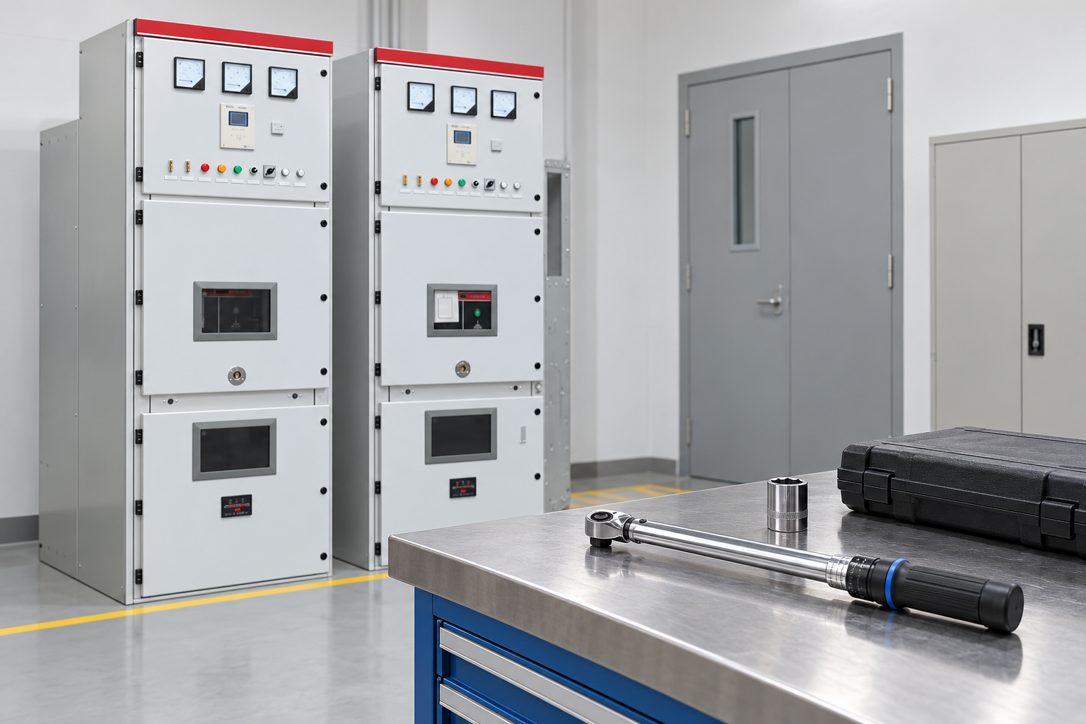
Contact preparation is part of the joint design. Do not assume every surface should be aggressively abraded until bright. Plated busbars and unplated conductors can require different treatment. Removing an intended finish may create a problem that tightening cannot correct.
Check for contamination, moisture, shipping damage, burrs and displaced insulation. If discoloration or corrosion is present, document its location and ask whether cleaning, reworking or replacement is authorized. Avoid guessing whether a visibly damaged contact area remains acceptable beneath the overlap.
Use only the specified cleaner or contact compound where required. A compound approved for one conductor interface may be unsuitable elsewhere. Keep its identity and application condition with the inspection record. Do not add grease to threads to make tightening easier unless the approved torque specification explicitly allows that condition.
Confirm bolt length, grade, nuts, flat washers and any spring or disc components against the drawing. Washer direction and quantity can be functional design details. A visually similar replacement may change bearing pressure or joint behavior. Procurement substitutions should receive engineering approval before installation.
Ensure the parts align without using bolt force to pull mispositioned busbars into place. Check supports and shipping-split alignment before final tightening. Mechanical stress from poor alignment can remain in the joint even when a wrench reaches its setting.
Do not reuse damaged hardware or assume every fastener is reusable after disassembly. The equipment instructions should determine replacement requirements. Preserve the difference between a manufacturer-approved replacement kit and assorted hardware chosen only because it fits the holes.
Use a tool with an appropriate working range and a valid calibration status. Confirm the units on both the instruction and the tool. N·m, lbf·ft and lbf·in are different units; a familiar-looking number is not sufficient. Any unit conversion should be checked before work begins and recorded clearly.
Access can require sockets, extensions or special adapters. Some arrangements affect the effective torque or the ability to apply force correctly. Use the tool and adapter instructions, and obtain approval when the normal method cannot be followed. Do not improvise a correction factor from memory.
Follow the specified tightening sequence and staging for multi-bolt joints. Record the setting and completion at the identified connection. Witness marks can help identify movement or completion, but paint across a bolt and nut does not prove the correct torque, contact condition or calibration was used.
Busbar assembly and intrusive inspection should occur under the site’s approved de-energized work arrangements. Identify all possible sources, including backfeeds, generators, stored energy and linked equipment. An open breaker indication alone does not establish a safe working condition.
The UK HSE’s guidance on work on electrical equipment discusses planning work and controlling relevant energy sources. It is background guidance, not a complete method statement for every project. The responsible site organization must define permits, isolation, verification and authorization for its installation.
Do not reach into an energized cubicle with a torque wrench to investigate a thermal concern. Any operating thermal survey and any intrusive corrective work require different planning. Record the condition first and have the responsible personnel determine the safe investigation scope.
A complete assembly record shows what was installed and how. It does not eliminate the need for the specified acceptance tests. Conversely, an acceptable electrical measurement does not prove every bolt was assembled correctly. Keep the two records connected to the same joint identifiers.
The switchgear contact resistance test guide covers the electrical measurement task. Test setup, instrument condition and comparison basis affect interpretation. Do not invent a single resistance acceptance value for every busbar connection or infer clamp load directly from a meter reading.
For later operating observations, use the busbar temperature-rise guide as related background. Compare conditions with the applicable design and test basis. A single thermal image taken at an unspecified load cannot validate every future operating condition.

If inspection reveals heat damage, movement or an unexplained measurement difference, preserve the evidence. Note operating load, phase, location, environmental conditions and the inspection method. Arrange the safe investigation before disturbing the connection. Retightening first can erase useful evidence without resolving the underlying fault.
Possible investigation areas include surface condition, assembly history, incorrect hardware, conductor stress and abnormal loading. These are questions to resolve, not a diagnosis from a photograph. The approved corrective action may involve disassembly, replacement, re-preparation and repeat testing rather than an additional pull on the wrench.
Do not confuse breakaway torque with original installation torque. The force needed to begin moving an existing fastener is affected by its current condition. An unapproved “check” can also move the fastener and change the joint. Follow the equipment’s defined inspection or verification method.
For new equipment, ask the supplier to identify all site-assembled interfaces and provide the required hardware, drawings, settings and preparation instructions. Confirm whether specialist supervision or factory witness points apply. Include shipping splits and extension joints in the delivery review, not just factory-closed compartments.
Shenheng’s KYN28 switchgear product page is a starting point for discussing the equipment and project interfaces. Product appearance does not establish a particular torque schedule. Request instructions for the exact approved configuration.
Retain the joint register, tool references, inspection results, deviations and corrective-action closure with the switchgear preventive maintenance records. That record lets future maintenance distinguish an original assembly issue from a later change. It also prevents the next team from treating an undocumented paint mark as the whole acceptance history.
NEMA’s demonstration below introduces disciplined conductor-terminal tightening. Its terminal example illustrates tool use and instruction-following; it does not supply torque values or an assembly sequence for a medium-voltage busbar splice.
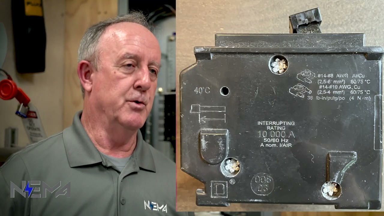
Further learning: How to Properly Torque a Conductor Terminal – NEMA — NEMAVue. Educational background; this is not an operating authorization. Open the video on YouTube.
No. The approved value depends on the joint design, hardware, finish and specified assembly condition. Use the manufacturer’s instructions for the identified connection.
No. Lubrication changes the torque-to-clamping relationship. Use only the condition and products authorized by the joint instructions.
No. It can support completion tracking, but it does not establish contact preparation, correct hardware, calibration or the actual assembly procedure.
No. Arrange a safe investigation and follow the approved repair procedure. Extra torque can damage components and may leave the original cause unresolved.