Shenheng Power Equipment Co., Ltd.
- Home
- Products
Products
Since 2001, Shenheng Power has been a trusted manufacturer of power transmission and distribution equipment, delivering reliable electrical solutions globally.
- Solutions
- News & Blog
- Service
- About Us
- Contact Us
Since 2001, Shenheng Power has been a trusted manufacturer of power transmission and distribution equipment, delivering reliable electrical solutions globally.
An isolation transformer and a step-down transformer describe different properties. Isolation describes separation between input and output windings; step-down describes an output voltage lower than the input. A transformer can provide both. For an industrial purchase, specify the voltage ratio and the required winding separation independently, then coordinate earthing, protection, insulation and load duty. A label saying “step-down” does not establish galvanic isolation, and a label saying “isolation” does not establish the output voltage or make exposed conductors safe to touch.
The first question is what voltage the connected equipment requires. The second is whether the source and load circuits must be conductively separated by the transformer windings. These questions belong on different lines of the enquiry. Combining them into one informal equipment name invites suppliers to answer different requirements while appearing to quote the same item.
A two-winding transformer can reduce voltage while maintaining separation between its windings. A one-to-one isolation transformer can keep approximately the same voltage. An autotransformer can reduce voltage through a shared winding connection. These arrangements should be identified on the approved diagram, including any shields and connections to earth. Exterior tank shape cannot distinguish them reliably.
For a broader connection comparison, read the autotransformer and two-winding transformer guide. This article focuses on interpreting isolation and voltage-reduction requirements together, rather than comparing every transformer topology.
| Specification question | Isolation requirement | Step-down requirement | Evidence to request |
|---|---|---|---|
| What must the equipment do? | Separate the input and output winding circuits | Deliver a lower nominal output voltage | Connection diagram and rated voltage schedule |
| Is the voltage ratio defined by the name? | No; it may be one-to-one or another ratio | It establishes direction, not the exact ratio | Input, output and tap ratings |
| Does the name establish safe earthing? | No; the installation still needs a designed arrangement | No; reduced voltage alone does not define protection | Earthing and protection drawings |
| Can the two requirements coexist? | Yes, with an appropriate separate-winding design | Yes, when the selected construction also provides separation | Approved manufacturer documentation |
| Does it establish suitability for the load? | No | No | Load data, thermal rating and application review |
This is a specification comparison, not a certification table. Special applications can impose construction, test and installation requirements beyond these basic descriptions. Do not infer medical, marine or testing-bench approval from a generic isolation designation.
For the ideal two-winding model, the voltage relationship is Vs / Vp = Ns / Np, where V is voltage and N is winding turns. The subscripts identify secondary and primary. Fewer secondary turns give a lower secondary voltage. The OpenStax transformer lesson explains the relationship and its ideal assumptions.
For example, an ideal single-phase transformer supplied at 480 V with half as many secondary turns would have 240 V at the secondary. This is an explanatory calculation, not a proposed product rating. Real terminal voltage changes with supply variation, tap position, load and impedance. A three-phase specification also needs the winding connection and the relationship between phase and line quantities.
The turns calculation does not determine isolation performance. It also does not provide a complete thermal design or establish the available fault current. A purchaser should request the actual rated output, acceptable variation and loading basis, rather than using an ideal ratio to promise operating voltage at every condition.
Winding separation removes an intentional conductive connection through the transformer between the input and output winding circuits. It does not mean that every part of the installation is floating. Enclosures, shields, protective conductors, neutral connections and external equipment can create additional paths that must be understood in the system design.
Ask the manufacturer to identify the winding terminals and any electrostatic shield separately. A shield terminal has a different function from an output neutral. Their treatment should follow the approved installation design. An optional shield is not a substitute for the specified insulation system, and its presence does not prove a particular interference-reduction result.
Do not conduct improvised continuity experiments on energized equipment. Documentation review and approved acceptance tests should establish what was supplied. Any necessary electrical testing belongs to competent personnel working under the equipment instructions and the site’s safe procedures.
Isolation can support a particular protective arrangement, but it does not eliminate electrical hazards. Touching both secondary conductors can still complete a dangerous circuit. The UK HSE’s guidance on safety in electrical testing specifically discusses limitations of isolating transformers in testing environments. Its context should not be converted into a blanket rule for industrial distribution systems.
Likewise, a lower secondary voltage is not automatically a harmless voltage. Environmental conditions, exposed conductive parts and the actual fault path matter. The designer must choose protection and earthing for the installation’s applicable rules and intended use. Devices should not be bypassed because the supply passes through equipment described as an isolation transformer.
Maintenance isolation is a separate process. Switching off a control circuit, or disconnecting one presumed source, may leave another energy source connected. HSE’s guidance on work on electrical equipment emphasizes planning and isolation of relevant sources. A transformer product name cannot replace that process.
Start with the load voltage, phase arrangement, frequency, continuous apparent power and operating schedule. Then identify starting currents, intermittent duty and nonlinear loads. A transformer serving electronics, drives or a mixed industrial load may require an application review beyond the sum of nameplate real power.
Also describe the supply conditions. A suitable voltage ratio at the nominal input may be unsuitable at the actual supply extremes. Frequency must be agreed; applying an inappropriate voltage-to-frequency condition can create a serious design problem. Do not assume that a transformer advertised for one supply frequency is interchangeable with another.
The enquiry should state ambient conditions, altitude, enclosure location, ventilation constraints and access for maintenance. These inputs help the manufacturer select and document a design. They do not justify guessing a derating percentage. Use the approved rating and operating limits for the delivered configuration.
The secondary circuit needs a defined protection concept. Identify the intended neutral treatment, protective conductor routes, disconnecting means and protective devices. Check coordination using the transformer impedance and the connected network, including any other sources that can energize the output circuit.
Separate windings do not imply unlimited fault-current reduction. An installation can still have substantial secondary fault current. Conversely, the transformer can change the characteristics used by downstream protection. The electrical designer should evaluate the actual fault conditions and required disconnection performance.
For the related upstream equipment, the transformer short-circuit withstand guide explains how specified duty and verification evidence fit together. Keep withstand capability, prospective current and protection settings as distinct items in the review. A successful ratio test cannot establish all three.
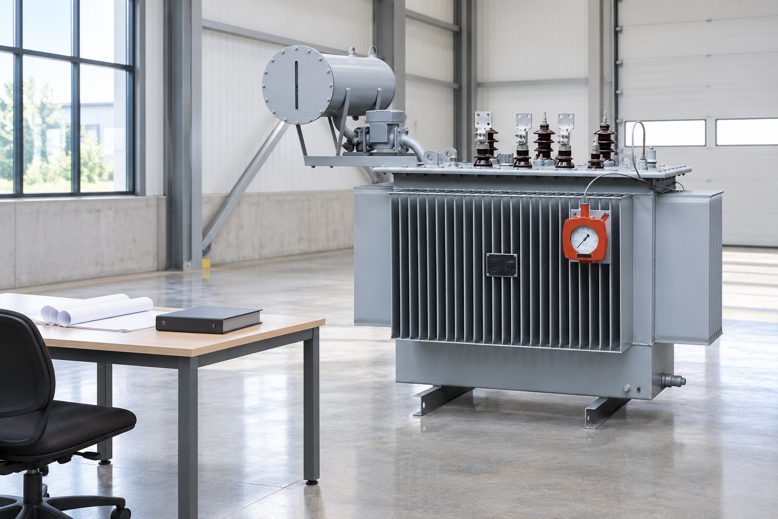
Ask for the rated voltage schedule, connection diagram, insulation information, thermal duty and the applicable test plan. Each record should identify the ordered design or delivered unit. A brochure for a product family is useful background, but approval should resolve the configuration actually being purchased.
Create a simple requirement-to-document register. Record where each requirement is answered, who reviewed it and which revision is accepted. If a drawing changes after approval, check whether it affects winding connections, terminals, shields, enclosure interfaces or protection assumptions. This makes a later substitution easier to assess.
Receiving inspection should compare identification, visible condition and supplied documentation. Acceptance testing must follow the agreed procedure and manufacturer limits. Do not apply a convenient insulation test voltage to an assembled installation without checking what else remains connected, including instruments, electronics and surge protection.
Instead of requesting “one isolation step-down unit,” write separate requirements for input and output voltage, frequency, phase, kVA, winding separation, connection arrangement and site conditions. State the governing specification and identify the documents required before manufacture. Ask suppliers to list departures explicitly.
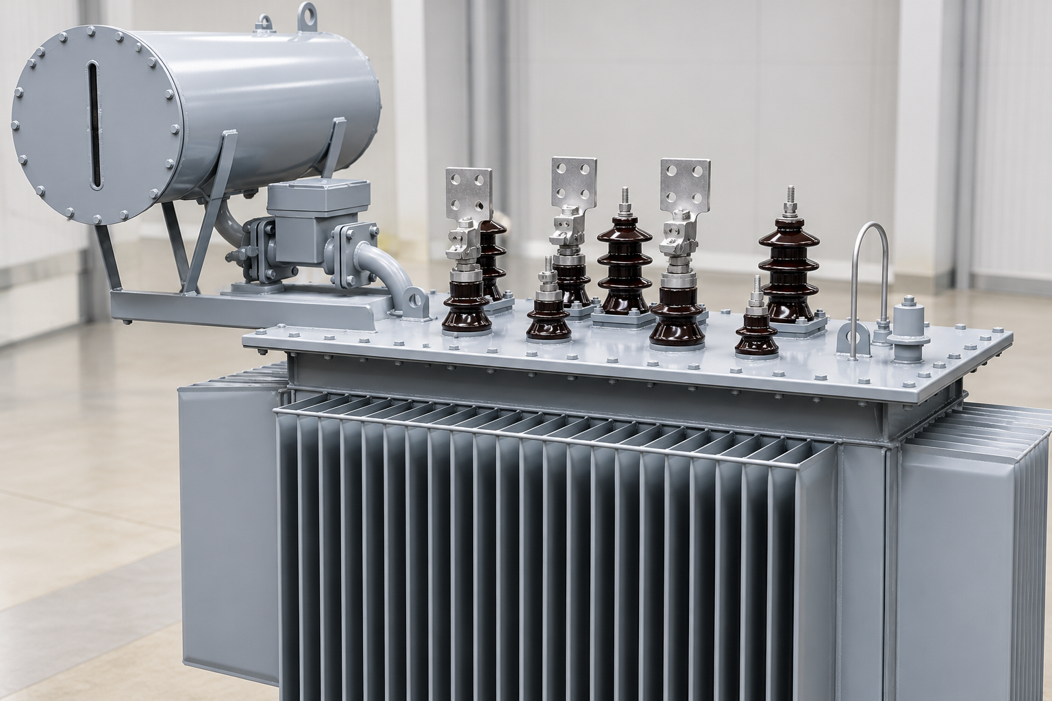
For an industrial transformer project, Shenheng’s oil-immersed transformer product page provides a starting point for an application discussion. The reference product photographs illustrate equipment context; they do not establish that a particular winding arrangement, material or isolation qualification has been supplied.
For an indoor dry-type option, coordinate the selected design with the dry-type transformer clearance guide. If project documents use different terminology, resolve the intended circuit behavior first and have all parties approve the same drawing. Clear requirements are more useful than choosing a product name that sounds comprehensive.
The university lecture below explains operating principles and construction of single-phase transformers. Use it to understand magnetic coupling and winding behavior. It is background education, not evidence that a specific supplied transformer meets an isolation or installation requirement.
Further learning: Mod-01 Lec-02 Lecture-02-Operating Principles and Construction of Single Phase Transformers — nptelhrd. Educational background; this is not an operating authorization. Open the video on YouTube.
Yes. An appropriate separate-winding design can reduce voltage and provide winding separation. Confirm both properties in the approved connection and insulation documentation, rather than relying on the step-down label alone.
No. Isolation describes winding separation. The selected ratio can be one-to-one, step-down or step-up, subject to the actual design and application requirements.
No. Contact between secondary conductors can still be dangerous, and external connections affect the protective arrangement. Follow the designed protection, earthing and safe working procedures.
No. Similar external equipment can contain different winding connections. Use the approved diagram, rating information and agreed verification records to establish the delivered arrangement.