Shenheng Power Equipment Co., Ltd.
- Home
- Products
Products
Since 2001, Shenheng Power has been a trusted manufacturer of power transmission and distribution equipment, delivering reliable electrical solutions globally.

- Solutions
- News & Blog
- Service
- About Us
- Contact Us
Since 2001, Shenheng Power has been a trusted manufacturer of power transmission and distribution equipment, delivering reliable electrical solutions globally.
Substation control building design should begin with the equipment and operating tasks the building must support, then resolve access, cable entry, batteries, environmental control and future changes. A floor plan that fits every cabinet can still fail if a relay cannot be maintained, a battery cannot be replaced, or a cable route blocks an exit. The useful deliverable is a coordinated layout with documented interfaces and acceptance evidence. This guide focuses on arranging the control house and its equipment; overall yard layout, battery capacity calculations and the construction sequence have separate engineering responsibilities.
List the functions to be housed: protection, control, communications, metering, auxiliary distribution, batteries and any other equipment specified by the owner. Identify which functions remain in outdoor cabinets or packaged equipment. Include the expected occupancy and maintenance activities, because a permanently staffed control room has different requirements from a normally unattended equipment building.
The University of Washington facilities design standards illustrate how an owner organizes requirements across disciplines and controls requests for a variance. Those campus requirements are not a universal substation specification. The useful project lesson is to agree the applicable design basis, responsible reviewers and exception process before coordinating the building layout.
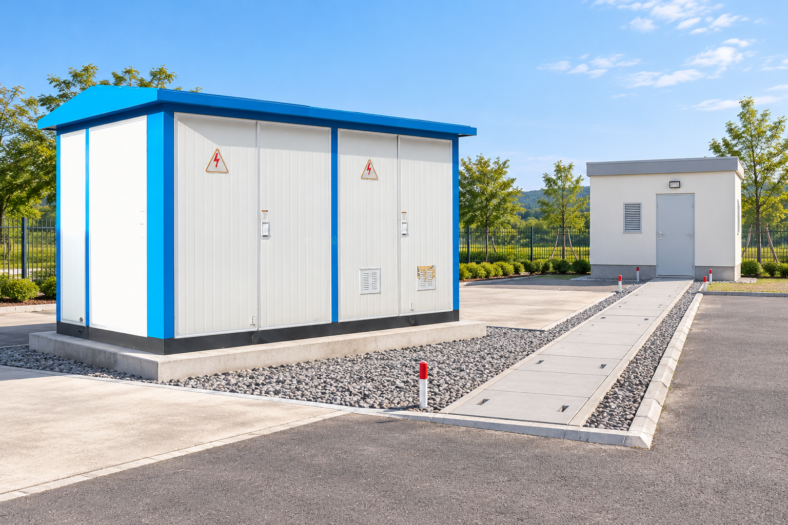
Shenheng’s compact outdoor substation is a packaged equipment arrangement. It should not automatically be treated as an occupied control building. Ask what the supplied package contains and where external protection, communications and auxiliary equipment will be located. The reference-based images here illustrate that interface rather than claim an unverified control-house interior.
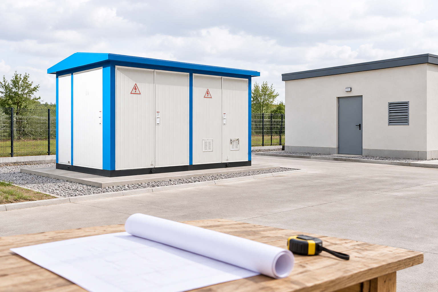
For the wider equipment boundary, use the substation equipment guide before separating the functions assigned to the control house.
For each cabinet or rack, obtain the footprint, height, weight, access sides and cable entry position. Add the space required by open doors, removable covers, service tools and replaceable components. A catalog width is not the whole operating envelope. Mark which dimensions are confirmed and which are provisional so the civil designer can recognize unresolved constraints.
The equipment schedule should also identify heat dissipation, environmental limits, auxiliary supply and communication interfaces. These items connect the electrical design to ventilation, cooling, building services and cable routing. If the selected equipment changes, review all those interfaces rather than simply moving its rectangle on the floor plan.
Reserve future positions only for an agreed expansion scenario. Record what the spare space is intended to accommodate and whether cable routes, power supplies and cooling provisions support it. An empty floor area behind existing panels may be physically available but unsuitable for the future equipment’s access or connections.
Separate normal observation, controlled testing, maintenance and replacement tasks on the layout. Identify the location from which operators read indications and the place where authorized personnel connect test equipment. Keep routes understandable and avoid arrangements that require people to pass through a different work area to reach an exit.
Consider cabinet doors in their open position, not just closed outlines. Opposing doors, temporary test benches and stored replacement parts can change an otherwise clear aisle. Review the most demanding credible task and document the assumed equipment state. The floor plan does not authorize work while energized; that requires the site’s electrical safety process.
Use the DOE electrical safety handbook as general program guidance, with the applicable current rules and site procedures governing the project. Do not copy a clearance from a low-voltage illustration into a medium-voltage installation without establishing its applicability. The designer and approving authority must resolve the correct requirements.
Battery type, arrangement and maintenance method influence more than the rack footprint. Obtain the battery supplier’s environmental and access requirements, assess applicable ventilation and safety provisions, and determine how units will be delivered and replaced. Do not assume that one battery chemistry’s room arrangement is appropriate for another.
Decide whether batteries share a room with other equipment only after the relevant engineering and safety review. Show barriers, access restrictions or separate areas where required by the approved design. Coordinate chargers and distribution panels with the battery location while retaining suitable access for inspection and replacement.
The existing substation battery sizing guide covers the load and autonomy basis; it does not size the battery room. Likewise, the substation DC system guide addresses the electrical supply arrangement. Use their confirmed equipment outputs as inputs to the building design and avoid reopening their calculations within the floor plan.
Map the destinations of power, control and communication circuits before fixing cable entries. Identify cabinet entry positions, routing arrangements, spare capacity and access for future work. The desired route should be feasible with the actual cables, their permitted bending and their installation method, rather than a single line connecting two points.
Coordinate separation and screening requirements with the responsible electrical and communications designers. Label the design basis instead of assigning an unsupported universal separation distance. Where routes cross or share an interface, record the approved arrangement and who is responsible for installing and inspecting it.
The building envelope also needs coordinated penetrations, sealing and drainage provisions. Follow the approved fire, weather and environmental design rather than improvising a site seal. Refer to the substation cable trench guide for the external route interface, then resolve how those routes enter and continue through the control house.
Compile heat loads from confirmed equipment data and distinguish continuous operation from temporary testing or occupied use. Include the environmental conditions specified for the site. The cooling or ventilation designer should assess the building envelope and operating conditions, not select equipment from a generic room area rule.
Identify how loss of environmental control will be detected and handled. The owner’s requirements may call for alarms, monitoring or particular resilience arrangements. Document the applicable requirement and testable response rather than claiming that a second cooling unit automatically guarantees availability.
Consider moisture, dust and corrosive exposure alongside temperature. The layout should support inspection and servicing of environmental systems without interfering with electrical equipment access. Place drains and building services through the coordinated design, with any risk to electrical equipment reviewed before construction.
| Interface | Information needed before layout release | Acceptance record |
|---|---|---|
| Protection and control panels | Confirmed cabinet envelope, service sides and entries | Approved equipment and layout drawings |
| Battery installation | Selected system, access and environmental requirements | Supplier documents and safety review |
| Cable entries | Route destinations, entry positions and sealing requirements | Coordinated penetration and cable drawings |
| Environmental systems | Equipment heat data and site design conditions | Approved calculation and control description |
| Equipment replacement | Largest replaceable item and handling method | Reviewed delivery and replacement route |
| Future extension | Defined equipment scenario and supporting services | Recorded expansion assumptions |
| Building release | Outstanding changes and responsible reviewers | Closed interface register and revised drawings |
The table organizes project decisions; it supplies no universal construction dimensions. Use the owner’s design basis, supplied equipment documents and applicable approval process to establish measurable criteria. Each unresolved entry needs a named owner and a due date before its related construction work is released.
Trace the route from the site entrance to the final equipment position. Include unloading, door openings, changes in level, turning space and temporary handling equipment. The route should work for the actual shipping arrangement, not only for the cabinet after unpacking. Coordinate floor loading and handling provisions with the structural designer.
Repeat the exercise for a future replacement when surrounding equipment is already installed. A panel that can enter an empty building may be impossible to remove after the room is filled. Record any intended removable wall section, access panel or other provision through the approved building design.
Keep the replacement route distinct from routine working space and emergency egress. A drawing note saying “clear area” is ambiguous if those functions require different conditions. Give each area a purpose and review any overlap so later operators understand what must remain available.
Equipment tests do not automatically verify the building arrangement. Add interface checks for cabinet access, identification, cable entries, environmental monitoring, auxiliary services and the records needed for operation. Confirm the final installed arrangement against the approved drawings and resolve differences through the project change process.
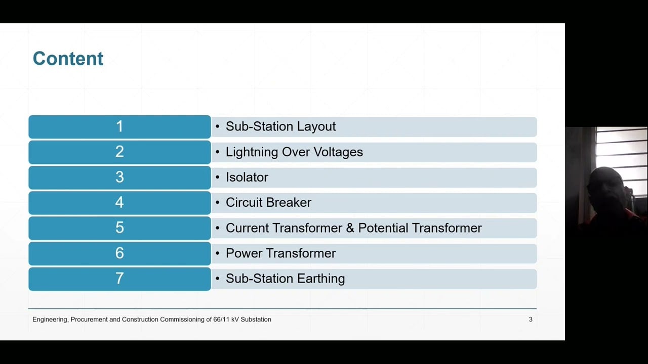
Further learning: Engineering, Procurement and Commissioning of 66/11 kV Substation: Session 1 — edupme . Educational background; this is not an operating authorization. Open the video on YouTube.
The engineering training session provides wider substation procurement and commissioning context. Use it to understand coordination responsibilities, while retaining the project’s own building requirements and test records as the acceptance basis. A training example is not a certificate for a particular installation.
Separate installation acceptance from permission to energize. The substation construction sequence guide describes that project handover boundary. For the control house, preserve the final layout, equipment schedule, cable documentation, environmental settings and maintenance access assumptions before handing the building to the owner.
Before release, collect reviews from the responsible electrical, protection, communications, mechanical, civil and operating parties. Ask each reviewer to resolve the interfaces within their scope. A combined drawing is useful only when its dimensions and assumptions refer to the same equipment revision.
During procurement, require suppliers to report changes that affect the building. A different cabinet depth, cable entry, heat dissipation or service method can invalidate an accepted arrangement. Track the change and its consequences rather than relying on an informal assurance that the replacement is equivalent.
The final drawing set should identify permanent access areas, equipment references, route interfaces and controlled expansion assumptions. Keep a readable inspection and maintenance plan with it. This turns the layout into a useful operating record and reduces the chance that later storage, additions or replacements undermine the original arrangement.
Not automatically. A compact substation is a packaged equipment arrangement; a control building houses the functions defined by the owner. Confirm the contents and interfaces of each package before planning rooms.
No. Include service access, door movement, cable entries, environmental systems, delivery and replacement routes, and the applicable working-space and egress requirements.
The arrangement depends on the selected system, supplier requirements, applicable rules and the project’s safety review. Do not apply one battery type’s arrangement to every installation.
Use a coordinated layout and equipment schedule supported by a closed interface register. Identify the confirmed document revisions, unresolved changes and responsible approving parties.