Shenheng Power Equipment Co., Ltd.
- Home
- Products
Products
Since 2001, Shenheng Power has been a trusted manufacturer of power transmission and distribution equipment, delivering reliable electrical solutions globally.

- Solutions
- News & Blog
- Service
- About Us
- Contact Us
Since 2001, Shenheng Power has been a trusted manufacturer of power transmission and distribution equipment, delivering reliable electrical solutions globally.
For a three-phase transformer, full-load line current equals rated kVA multiplied by 1,000 and divided by the square root of three times line-to-line voltage. For a single-phase transformer, divide rated VA by voltage. Always calculate the primary and secondary separately using their own rated voltages. This guide gives project engineers, EPC teams and buyers a practical way to define inputs, compare options and document the final decision. It focuses on the search task behind transformer full load current calculation without replacing approved studies, local rules, manufacturer drawings or qualified engineering judgment.
For a three-phase transformer, full-load line current equals rated kVA multiplied by 1,000 and divided by the square root of three times line-to-line voltage. For a single-phase transformer, divide rated VA by voltage. Always calculate the primary and secondary separately using their own rated voltages.
The important point is to keep the electrical boundary consistent. Ratings on a single-line diagram, an equipment nameplate, a study report and a quotation may describe different operating cases. Before comparing them, confirm voltage, frequency, number of phases, grounding method, normal switching arrangement, contingency state and the date of the source data.
For procurement, translate the engineering conclusion into verifiable requirements. Ask the supplier to identify the applicable standard, declared rating, tested configuration, drawings, tolerances and documents that will be submitted for approval. Avoid accepting a broad statement such as “suitable for the system” when the actual duty has not been listed.
Rated Kva must be defined from the approved design basis rather than inferred from a product family name. For transformer full load current calculation, record the source document, operating case and boundary to which this item applies. This prevents a correct value from being used in the wrong part of the system.
Review the item against connected equipment and future configurations. A change in source strength, cable route, enclosure, protection setting, ambient condition or operating sequence can alter the conclusion. Where the information is provisional, mark it clearly and require confirmation before procurement or energization.
Primary Voltage must be defined from the approved design basis rather than inferred from a product family name. For transformer full load current calculation, record the source document, operating case and boundary to which this item applies. This prevents a correct value from being used in the wrong part of the system.
Review the item against connected equipment and future configurations. A change in source strength, cable route, enclosure, protection setting, ambient condition or operating sequence can alter the conclusion. Where the information is provisional, mark it clearly and require confirmation before procurement or energization.
Secondary Voltage must be defined from the approved design basis rather than inferred from a product family name. For transformer full load current calculation, record the source document, operating case and boundary to which this item applies. This prevents a correct value from being used in the wrong part of the system.
Review the item against connected equipment and future configurations. A change in source strength, cable route, enclosure, protection setting, ambient condition or operating sequence can alter the conclusion. Where the information is provisional, mark it clearly and require confirmation before procurement or energization.
Three-Phase Square-Root Factor must be defined from the approved design basis rather than inferred from a product family name. For transformer full load current calculation, record the source document, operating case and boundary to which this item applies. This prevents a correct value from being used in the wrong part of the system.
Review the item against connected equipment and future configurations. A change in source strength, cable route, enclosure, protection setting, ambient condition or operating sequence can alter the conclusion. Where the information is provisional, mark it clearly and require confirmation before procurement or energization.
Line Current must be defined from the approved design basis rather than inferred from a product family name. For transformer full load current calculation, record the source document, operating case and boundary to which this item applies. This prevents a correct value from being used in the wrong part of the system.
Review the item against connected equipment and future configurations. A change in source strength, cable route, enclosure, protection setting, ambient condition or operating sequence can alter the conclusion. Where the information is provisional, mark it clearly and require confirmation before procurement or energization.
Continuous Equipment Rating must be defined from the approved design basis rather than inferred from a product family name. For transformer full load current calculation, record the source document, operating case and boundary to which this item applies. This prevents a correct value from being used in the wrong part of the system.
Review the item against connected equipment and future configurations. A change in source strength, cable route, enclosure, protection setting, ambient condition or operating sequence can alter the conclusion. Where the information is provisional, mark it clearly and require confirmation before procurement or energization.
| Input or decision point | Where to obtain it | How to use it |
|---|---|---|
| Three-phase current | I = kVA × 1000 /(√3 × VLL) | Use line-to-line voltage |
| Single-phase current | I = kVA × 1000 / V | Do not include √3 |
| Primary current | Use primary rated voltage | Relevant to upstream equipment |
| Secondary current | Use secondary rated voltage | Relevant to LV bus and cables |
| Design current | Apply project loading and code rules | Not always identical to nameplate current |
A 1,000 kVA, 11 kV three-phase winding has a rated line current of 1,000,000 divided by 1.732 × 11,000, or about 52.5 A. At 400 V, the corresponding rated current is about 1,443 A. These are nominal rated currents and do not set protection by themselves.
A useful calculation sheet shows inputs first, then conversions, intermediate results and the final selection. Keep manufacturer guarantees separate from planning estimates. If a result changes materially when a reasonable assumption changes, identify that sensitivity in the design review instead of presenting one number as certain.
For calculation topics, retain the unrounded result until the final selection step and state units beside every value. For comparison topics, use the same service conditions for both options. For classification topics, quote the complete marking and tested installation conditions rather than extracting one attractive rating.
Provide the project single-line diagram and a concise data sheet. State the service voltage, frequency, phases, system grounding, continuous duty, short-circuit duty, environment, installation location, enclosure, auxiliary supplies, communication needs and applicable document hierarchy. Identify which values are guaranteed and which are for information.
Request outline and foundation drawings, terminal details, heat-loss information, lifting data, protection and control diagrams, test plan, routine test reports, certificates relevant to the stated rating, installation instructions, maintenance information and recommended spare parts. The supplier should list every deviation from the enquiry instead of silently substituting a standard arrangement.
Shenheng’s transformer product page can support a project enquiry, but the final configuration, ratings and accessories must be confirmed in the approved technical offer. Use the broader transformer guide to understand the parent equipment category.
This article is for planning and technical review. Electrical studies, switching, testing, installation and maintenance must be performed by qualified people under the site’s approved safety program. Identify all normal, alternate, induced and stored-energy sources before work begins. Apply the required isolation, absence-of-voltage verification, grounding and approach controls.
Do not use a blog value as an acceptance limit. Apply the edition of the standard named by the contract, the authority having jurisdiction, the manufacturer’s instructions and the approved project specification. Where documents conflict, record the issue and obtain a formal technical resolution.
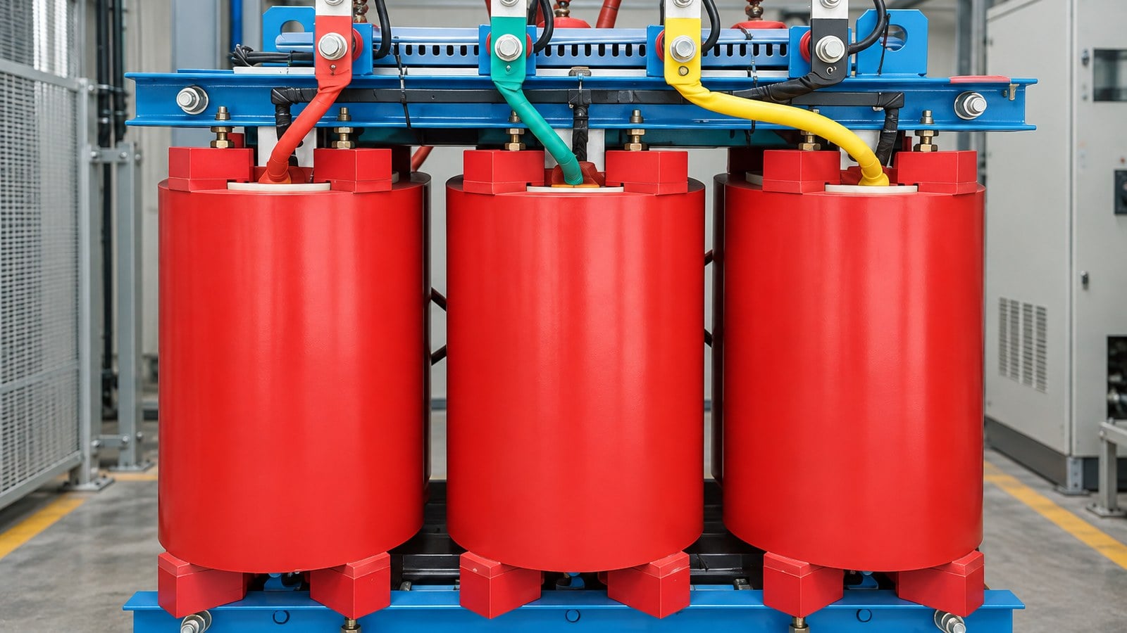
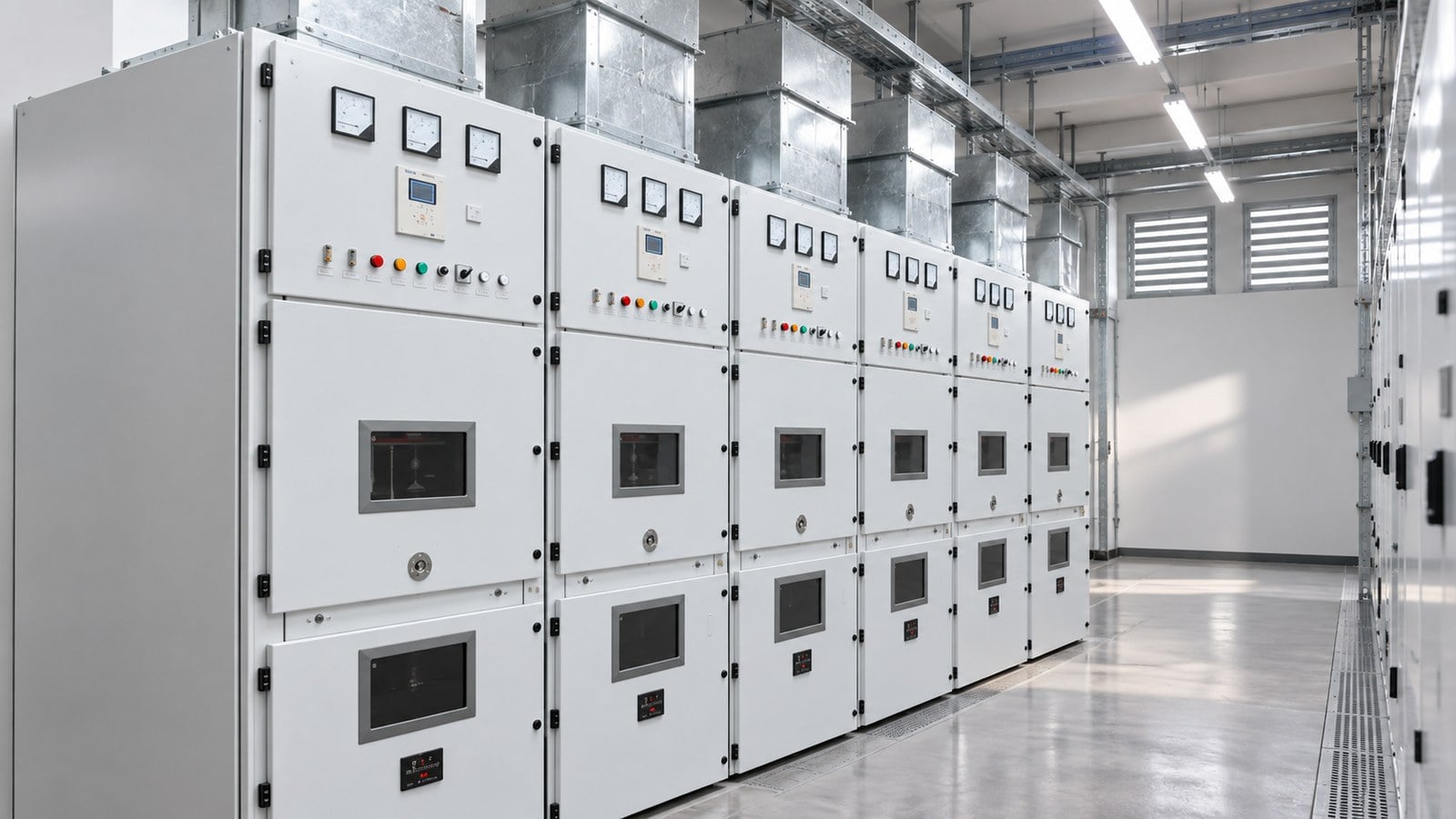
Generated equipment images in this article are based on real Shenheng product photographs and illustrate planning context only. They are not wiring diagrams, certified construction drawings or evidence of a supplied project configuration.
Use the project-specific editions and local requirements. These neutral sources provide further safety, grid and measurement context:
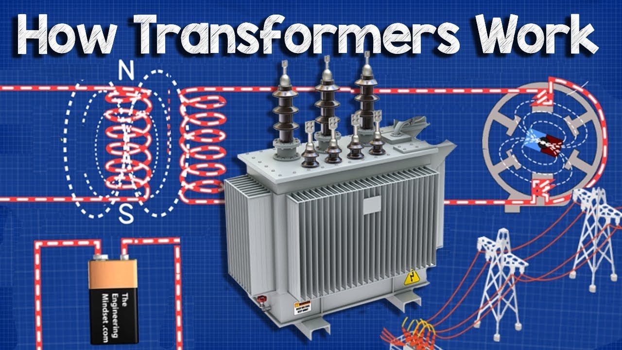
How Does a Transformer Work? by The Engineering Mindset provides a visual introduction to the equipment context. The article remains complete without the video.
Confirm the project boundary, operating case, equipment identity and governing design documents before using a rating, formula or comparison.
No. Voltage class, equipment design, environmental conditions, protection philosophy and local requirements can change the answer. Confirm the final choice with the project engineer and manufacturer.
State the system voltage, ratings, fault duty, environment, operating sequence, applicable standards, required drawings, tests, documentation and any future expansion requirement relevant to the topic.
List every assumption beside its source and planned confirmation date. Recalculate the result when verified utility, load, protection or site information becomes available.
No. It supports early planning and review, but final electrical design and work controls must be completed by qualified personnel using approved project data.
For a three-phase transformer, full-load line current equals rated kVA multiplied by 1,000 and divided by the square root of three times line-to-line voltage. For a single-phase transformer, divide rated VA by voltage. Always calculate the primary and secondary separately using their own rated voltages. A defensible project result connects the chosen rating or arrangement to traceable inputs, credible operating scenarios, coordinated equipment and evidence that can be verified before energization. That record is more valuable than a generic rule because it remains understandable when the system changes.