Shenheng Power Equipment Co., Ltd.
- Home
- Products
Products
Since 2001, Shenheng Power has been a trusted manufacturer of power transmission and distribution equipment, delivering reliable electrical solutions globally.

- Solutions
- News & Blog
- Service
- About Us
- Contact Us
Since 2001, Shenheng Power has been a trusted manufacturer of power transmission and distribution equipment, delivering reliable electrical solutions globally.
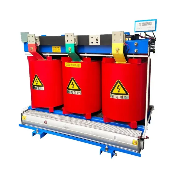
Transformer impedance is the bridge between a power transformer’s nameplate and the current a switchboard may see during a fault. It also determines how two transformers divide load when they share a bus. The calculations below are screening tools; a protection, arc-flash or equipment-duty study must include the complete network.
Percent impedance (%Z) is the voltage, expressed as a percentage of rated voltage, needed to circulate rated current with the other winding shorted during the impedance test. In per-unit form, 5%Z is 0.05 pu. Lower impedance generally means better voltage regulation, but it also permits more short-circuit current. The value must be read with rated kVA, voltage, frequency, vector group and tap position.
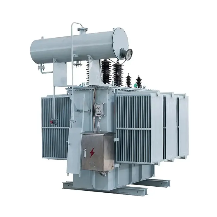
For a balanced three-phase, transformer-only approximation:
text

I_fault ≈ I_rated / Z_pu

S_sc   ≈ S_transformer / Z_pu
Example (illustrative, not a Shenheng rating): a 1,000 kVA, 11 kV transformer with 5%Z has rated current of about 52.5 A on the 11 kV side. Dividing by 0.05 gives roughly 1.05 kA, or about 20 MVA fault level at the terminals before source, cable and motor impedance are added.
| Change | First-pass effect | What the engineer still checks |
|---|---|---|
| %Z falls from 6% to 5% | Prospective current rises | Upstream impedance, X/R, breaker interrupting duty |
| Transformer kVA increases at same %Z | Fault MVA and current increase | Bus bracing, protection coordination |
| Cable is added between transformer and bus | Fault current at the bus decreases | Cable length, conductor geometry, temperature |
Do not convert this estimate directly into a breaker rating. The actual study adds utility fault level, generator/motor contribution, grounding method, X/R and the worst operating configuration.
Before closing a tie, verify all of the following:
For two units on a common bus, an initial sharing estimate is inversely proportional to their leakage impedances:
text

I1 / I2 ≈ Z2 / Z1
If equal-kVA units have 5%Z and 6%Z, the 5%Z unit tends to carry about 6/5 (1.2) times the current of the 6%Z unit, before tap, temperature and circulating-current effects. Treat this as a study starting point, not a guaranteed field result.
Ask the OEM or utility for:
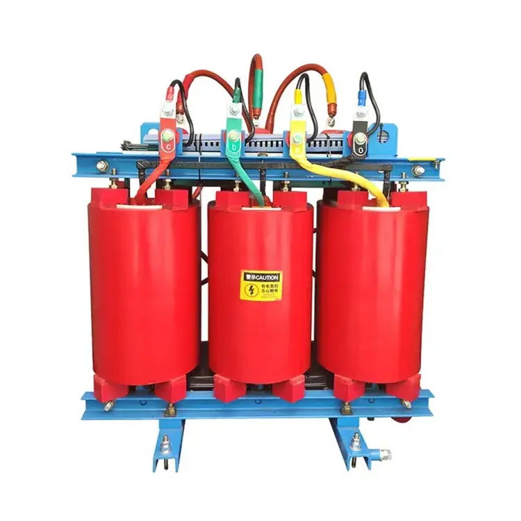
Shenheng Power’s transformer product family is the appropriate next path when you need to request these fields for a dry-type or oil-immersed power transformer. The category link does not establish a particular model’s %Z, fault duty or parallel compatibility. Include your one-line diagram, study voltage base, utility fault level and required tap/grounding details so the supplier can return a checkable datasheet.