Kể từ năm 2001, Shenheng Power đã là nhà sản xuất thiết bị truyền tải và phân phối điện đáng tin cậy, cung cấp các giải pháp điện năng đáng tin cậy trên toàn cầu.
Được hỗ trợ bởi hệ thống hậu mãi toàn diện, chúng tôi cung cấp dịch vụ tư vấn kỹ thuật chuyên gia, hướng dẫn sản phẩm và các dịch vụ OEM & ODM linh hoạt cho các dự án của bạn.
Kể từ năm 2001, Shenheng Power đã là nhà sản xuất thiết bị truyền tải và phân phối điện đáng tin cậy, cung cấp các giải pháp điện năng đáng tin cậy trên toàn cầu.
Transformer Pressure Relief Device: Function and Inspection
Release Time: 2026-10-16
A transformer pressure relief device opens a controlled discharge path when internal tank pressure reaches the device’s operating condition. Its purpose is to reduce the risk of tank damage; it does not identify the fault, remove the electrical energy feeding it, or make the transformer safe to restart. Procurement and inspection therefore need to consider the mechanical device, its discharge arrangement, its indication and contacts, and the protection scheme together. This guide explains what to request and record for an oil-filled transformer, without treating a generic device description as an installation or live-work procedure.
Establish which enclosure the device protects
Start with the transformer general arrangement and accessory schedule. Identify the main tank, any separate tap-changer compartment, and the manufacturer’s designated relief arrangement for each applicable enclosure. A device on one compartment should not be assumed to protect another compartment. Similarly, the presence of a conservator or an oil-level gauge does not establish the pressure relief specification.
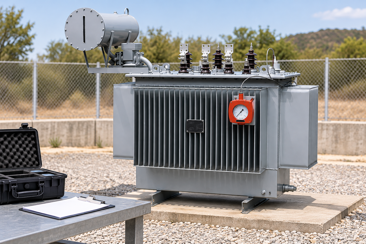
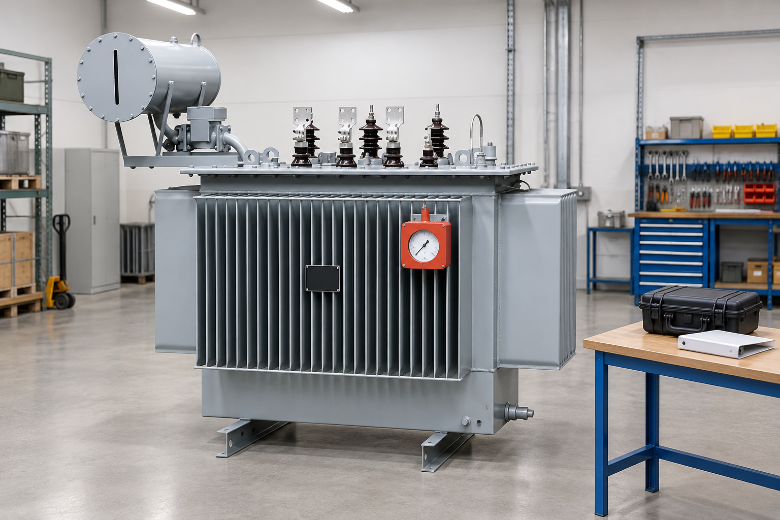
For Shenheng’s máy biến áp ngâm dầu, obtain the ordered accessory drawing before identifying an individual protection device. A catalog photograph establishes the equipment family, not every supplied accessory. The reference-based images in this article show the transformer context and do not identify an unverified valve on the pictured equipment.
The purchase specification should distinguish a sealed distribution tank from a conservator arrangement and record the intended installation environment. Check the actual insulating fluid, tank construction and equipment instructions rather than assuming every oil-filled transformer uses the same device. If an accessory list uses both PRV and PRD terminology, ask the supplier to define those terms for the offered assembly.
Preserve equipment condition and event evidence before resetting indications. Reference-based illustration.
Use the broader oil-immersed transformer procurement guide to establish the complete equipment requirements, then resolve the relief accessory within that approved package.
Understand the mechanical function and its limits
Some relief designs open and subsequently reclose; other arrangements require replacement of an operated element. Determine the supplied design from the device manual. Do not infer resetting instructions from another manufacturer’s similar-looking housing. An operated visual indicator may retain evidence after a reclosing mechanism has returned to its normal position.
The Bureau of Reclamation’s transformer maintenance and diagnostics manual describes pressure relief mechanisms and stresses the need to investigate an operation before returning equipment to service. Its examples are useful for understanding the function, but the ordered transformer and accessory documentation must establish the applicable settings and maintenance method.
There is no universal pressure value that can safely be copied into a purchase order. The transformer designer needs to coordinate the relief arrangement with the tank and application. Ask for the specified operating characteristic, relevant tolerances and the manufacturer’s acceptance evidence. A replacement with the same connection size is not automatically equivalent: the mechanism, materials, discharge behavior and indication can differ.
Separate relief from other transformer protection
A pressure relief device provides a mechanical response to pressure. A sudden-pressure relay detects a condition for electrical protection; it is not simply another name for a discharge valve. A Buchholz relay applies to an appropriate oil path between a tank and conservator and has a different operating basis. Differential protection uses electrical measurements. These functions may complement one another without being interchangeable.
Use the existing Buchholz relay working principle guide for the conservator gas and oil-surge function, and the transformer differential protection guide for the electrical protection boundary. Keeping the functions distinct helps a purchaser avoid specifying a contact arrangement as though it replaced the mechanical relief requirement.
Whether a relief contact produces an alarm, a trip, or both is a scheme decision documented in approved drawings. This article does not recommend a universal contact-to-trip connection. The responsible protection engineer should identify the applicable device, contact behavior, auxiliary supply and relay logic, then verify the complete path under a controlled test procedure.
Procurement checks that prevent ambiguous quotations
Item to resolve
Evidence to request
Tại sao điều đó quan trọng
Protected compartment
Marked general arrangement and accessory list
Prevents treating one device as protection for unrelated enclosures
Supplied relief design
Device model and installation instructions
Establishes whether operation requires resetting, servicing or replacement
Operating characteristic
Manufacturer’s approved specification and acceptance record
Avoids substituting a generic pressure number
Mechanical connection
Flange, gasket and mounting drawing
Allows the transformer supplier to confirm fit and compatibility
Discharge arrangement
Direction and clearance drawing
Identifies nearby equipment and access routes affected by discharge
Contact and indication
Terminal schedule and contact description
Separates local evidence from remote alarm or trip logic
Inspection and spares
Maintenance instructions and approved replacement list
Supports future work without guesswork
This is a document review table, not a set of device limits. Use the ordered manufacturer’s instructions and approved project requirements for quantitative acceptance criteria. Record document revisions so an accessory change can be traced through the mechanical and protection drawings.
A quotation should also state who supplies any discharge accessories and who verifies their interface with the tank. Unclear responsibility can leave a relief device selected by one party and an enclosure or shield designed by another, without an agreed compatibility check. Resolve the interface before manufacture instead of relying on a site modification.
Review the discharge path before installation
Locate the device and the intended discharge direction on the arrangement drawing. Review nearby bushings, cabinets, cable routes, access points and containment provisions. The objective is to understand the consequences of discharge within the approved design, not to attach an improvised pipe or cover. Any addition that changes the device’s operating conditions requires manufacturer review.
The inspection viewpoint matters too. If a local indicator cannot be seen from the normal inspection position, define how its condition will be checked safely. Do not create a routine that requires someone to climb onto an energized transformer or approach exposed conductors. Equipment layout and inspection access should be resolved together.
Oil containment is a separate project interface. The transformer oil containment guide addresses civil and environmental coordination; it does not establish the relief device’s mechanical performance. Show both arrangements on the applicable drawings, and have the responsible parties resolve any conflicting assumptions about where discharged fluid can travel.
Inspect condition without disturbing the mechanism
During an authorized inspection, compare the equipment identity and observable condition with the approved baseline. Look for reported leakage, damage, corrosion, obstruction and evidence of an operated indicator. Describe what is visible and where it is located. Do not convert an unfamiliar indicator position into a diagnosis without the device instructions.
Keep photographs tied to a date, equipment identifier and viewing direction. A close photograph can document a condition, while a wider view establishes its location on the transformer. Preserve both where site rules allow photography. Do not touch, force, repaint or dismantle a relief assembly merely to obtain a clearer photograph.
Inspection frequency and maintenance scope should follow the equipment instructions and the owner’s maintenance program. Environmental exposure and service history may justify additional checks through that program, but this guide does not assign an unsupported calendar interval. Record the basis for any change, the responsible reviewer and the next planned inspection.
Verify contact and protection records using approved procedures. Reference-based illustration.
Verify indication, contacts and the protection record
A local indicator and an electrical contact can provide different evidence. Review the device manual to establish their behavior after operation and their permitted reset methods. Then compare the terminal schedule with the protection drawings. A label stating “pressure relief” does not demonstrate that the intended remote alarm is connected or that a trip path has been tested.
For commissioning, define the permitted test method before starting. The method should identify the equipment state, isolation, test points, acceptance criteria and restoration checks. Use authorized personnel and the manufacturer-approved procedure; do not artificially pressurize a tank or operate a relief mechanism using an improvised field test.
Record the observed local indication, contact state, relay response and control-room indication separately. If one part responds correctly and another does not, the record should expose that difference. A signed summary saying “PRD tested” is less useful than a traceable record of the particular functions verified and the drawings used.
Respond to an operation without erasing evidence
Treat a reported relief operation as an event requiring the owner’s response process. Secure the equipment state under approved procedures and preserve event information. Relevant records may include protection events, operating history, local observations, oil leakage and the device’s indication. Qualified personnel must decide what investigation and testing are required.
Resetting a visible indicator does not prove that the internal cause has been removed. Equally, an alarm record alone should not be treated as conclusive evidence of a particular internal fault. Compare independent observations before drawing a conclusion, and retain the original records rather than replacing them with a later interpretation.
Return-to-service authorization should identify who reviewed the evidence and which outstanding issues were resolved. The maintenance team, protection team and equipment manufacturer may each contribute different information. A clear handover prevents a mechanical reset from being mistaken for a complete release of the transformer.
Specify replacements and retain a useful handover pack
When a replacement is needed, request the approved part for the actual transformer and device revision. Match more than the physical opening: confirm the mechanical interface, fluid compatibility, indication, contacts and applicable operating specification. Record any manufacturer-approved substitution and update affected drawings before closing the work order.
The handover pack should contain the accessory schedule, installation instructions, wiring and terminal drawings, acceptance evidence, inspection baseline, maintenance requirements and spare-part identification. Link these records to the equipment identifier used by the site. A document stored under an unrelated model name is difficult to trust during an urgent investigation.
For new projects, discuss the accessory arrangement alongside the wider power transformer application rather than purchasing a relief device in isolation. The best procurement outcome is a coordinated tank, accessory, protection and inspection package with clearly assigned responsibilities.
Further learning and source boundaries
Further learning: Pressure Relief Device in Transformer | Transformer Pressure Relief Valve Working Principle | — Electrician Adda (Electric tech). Educational background; this is not an operating authorization. Mở video trên YouTube.
The educational video explains the pressure relief function; it is additional learning material, not permission to work on equipment. The Bureau of Reclamation transformer maintenance guide provides access to related transformer maintenance and diagnostics material. These general references support understanding, while the supplied equipment instructions determine the device-specific procedure.
Các câu hỏi thường gặp
Is a pressure relief device the same as a Buchholz relay?
No. Pressure relief provides a mechanical discharge response. A Buchholz relay detects conditions in an appropriate tank-to-conservator oil path. Confirm each function and its protection interface on the ordered equipment drawings.
Does an operated indicator mean the transformer can restart after resetting?
No. An indicator reset only changes the indication. The cause of the event and the equipment condition require investigation and authorized return-to-service review.
Can a replacement be selected from the flange size alone?
No. The approved operating specification, materials, mechanism, indication and contacts also need confirmation. Use the transformer manufacturer’s approved replacement or documented substitution.
What should a buyer request before accepting the accessory package?
Request the marked arrangement, device instructions, operating specification, terminal schedule, discharge interface, acceptance evidence and maintenance requirements, all tied to the supplied transformer and document revisions.
Shenheng Electric Power cam kết trở thành công ty dẫn đầu toàn cầu về các giải pháp thiết bị điện, giúp khách hàng đạt được quản lý điện năng an toàn, hiệu quả và bền vững.

 Công ty TNHH Thiết bị Điện Thâm Hằng.