2001 yılından bu yana Shenheng Power, güvenilir bir güç iletim ve dağıtım ekipmanları üreticisi olarak küresel çapta güvenilir elektrik çözümleri sunmaktadır.
2001 yılından bu yana Shenheng Power, güvenilir bir güç iletim ve dağıtım ekipmanları üreticisi olarak küresel çapta güvenilir elektrik çözümleri sunmaktadır.
Kesici ve Ayırıcı Bakımı: Kapsam, Kontrol Listesi ve Kayıtlar
Release Time: 2026-08-30
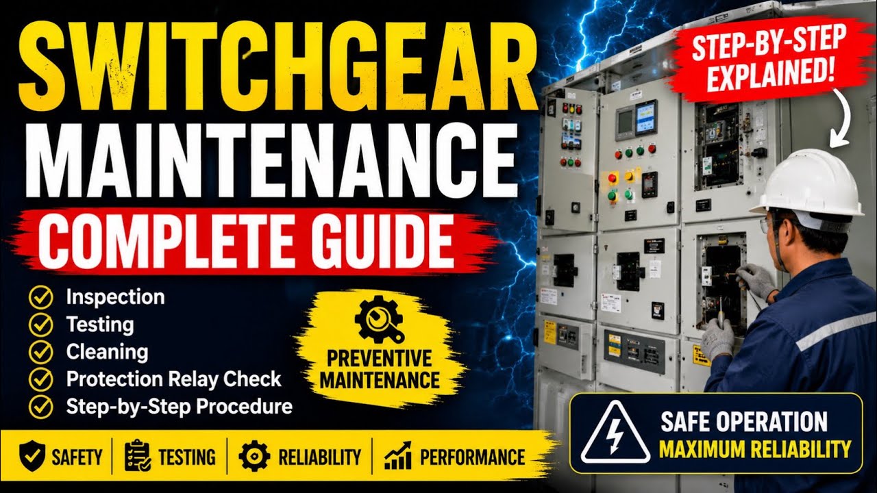
Switchgear preventive maintenance is a risk-based program of inspection, cleaning, mechanical exercise, testing, lubrication where specified, defect correction, and documentation performed before a failure occurs. A useful program is built from the equipment manufacturer’s instructions, duty and environment, previous condition, fault history, and the facility’s reliability requirements. It is not a generic annual checklist applied blindly to every cabinet. Medium- and low-voltage switchgear must be isolated and placed in an electrically safe work condition for intrusive work unless a justified energized task is covered by the site electrical-safety program.
What preventive maintenance is meant to prevent
Switchgear combines conductors, insulation, switching devices, protection, controls, interlocks, and enclosures. Failure can begin with contamination, moisture, loose connections, worn mechanisms, degraded insulation, blocked ventilation, incorrect settings, weak control power, or an enclosure that no longer protects as designed. Maintenance aims to find these conditions while corrective action is still planned rather than forced by an outage.
The program must distinguish inspection from testing. A visual check can find tracking or corrosion but cannot prove breaker timing. An infrared scan may show a hot connection under load but cannot assess hidden insulation. A relay self-test does not prove the entire current-transformer-to-trip-coil chain. Each technique answers a different question.
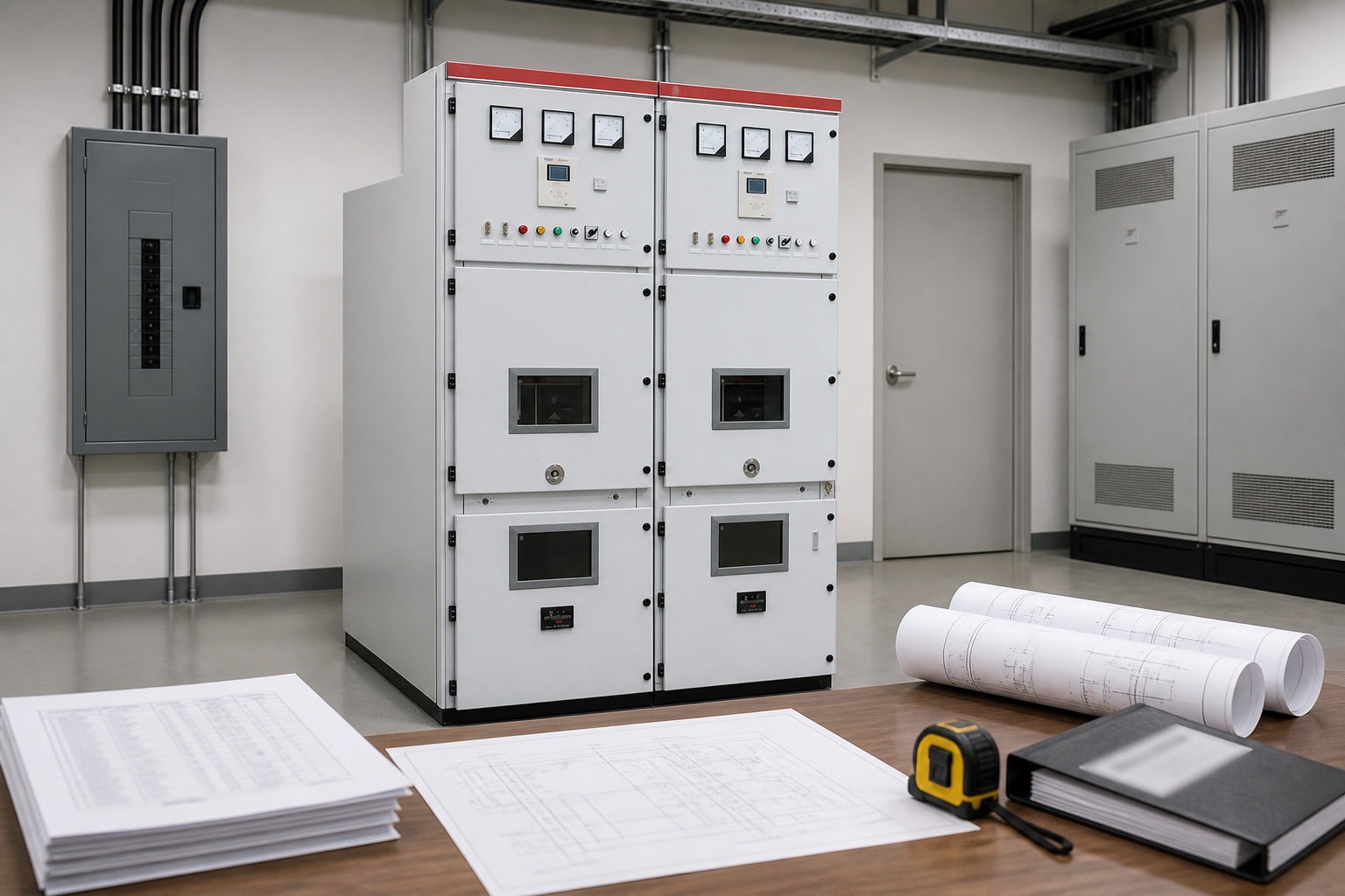
Maintain the switchgear against its approved drawings, ratings, protection study, and manufacturer instructions.
Maintenance scope by equipment area
Area
Typical checks
Evidence to record
Enclosure and environment
Water entry, dust, corrosion, heaters, ventilation, door seals
Photos, condition grade, corrective action
Primary conductors
Insulation, joints, barriers, supports, signs of heating or tracking
Calendar time is only one input. Increase attention where equipment experiences frequent operations, high fault duty, harsh dust, salt, humidity, condensation, corrosive vapor, vibration, high temperature, overload, or weak housekeeping. Critical feeders with no redundancy may justify online monitoring and shorter inspection intervals. Clean, lightly operated gear with stable condition data may follow a different plan, subject to the manufacturer and governing standard.
NFPA 70B provides a consensus framework for electrical equipment maintenance; information is available from the National Fire Protection Association. Where NETA standards are specified, use the contracted edition and qualified test organization. Regulatory safety requirements, equipment instructions, insurance requirements, and the owner’s engineering policy also apply.
Before the outage
Identify the exact lineup, sources, ties, generators, backfeeds, stored energy, and adjacent energized sections.
Review single-line diagrams, arc-flash labels, protection study, previous reports, open defects, alarm history, and operation counts.
Define the maintenance boundary and as-found tests before cleaning or adjustment.
Prepare approved switching, lockout/tagout, grounding, and restoration procedures.
Confirm test equipment, calibration, spares, lubricants, torque instructions, and manufacturer service information.
Coordinate operational consequences and contingency supply before removing the equipment from service.
After isolation, absence-of-voltage verification, discharge, and protective grounding as required, inspect before disturbing evidence. Look for soot, odor, cracked insulation, tracking, corona residue, loose hardware, displaced barriers, corrosion, pests, water marks, and foreign material. Record findings with location-specific photographs.
Use only manufacturer-approved cleaning methods. Compressed air can drive contamination deeper or spread conductive dust. Solvents may attack insulation. Abrasive cleaning can damage plated contacts. Correct the source of contamination or moisture; cleaning without fixing the ingress path merely resets the clock.
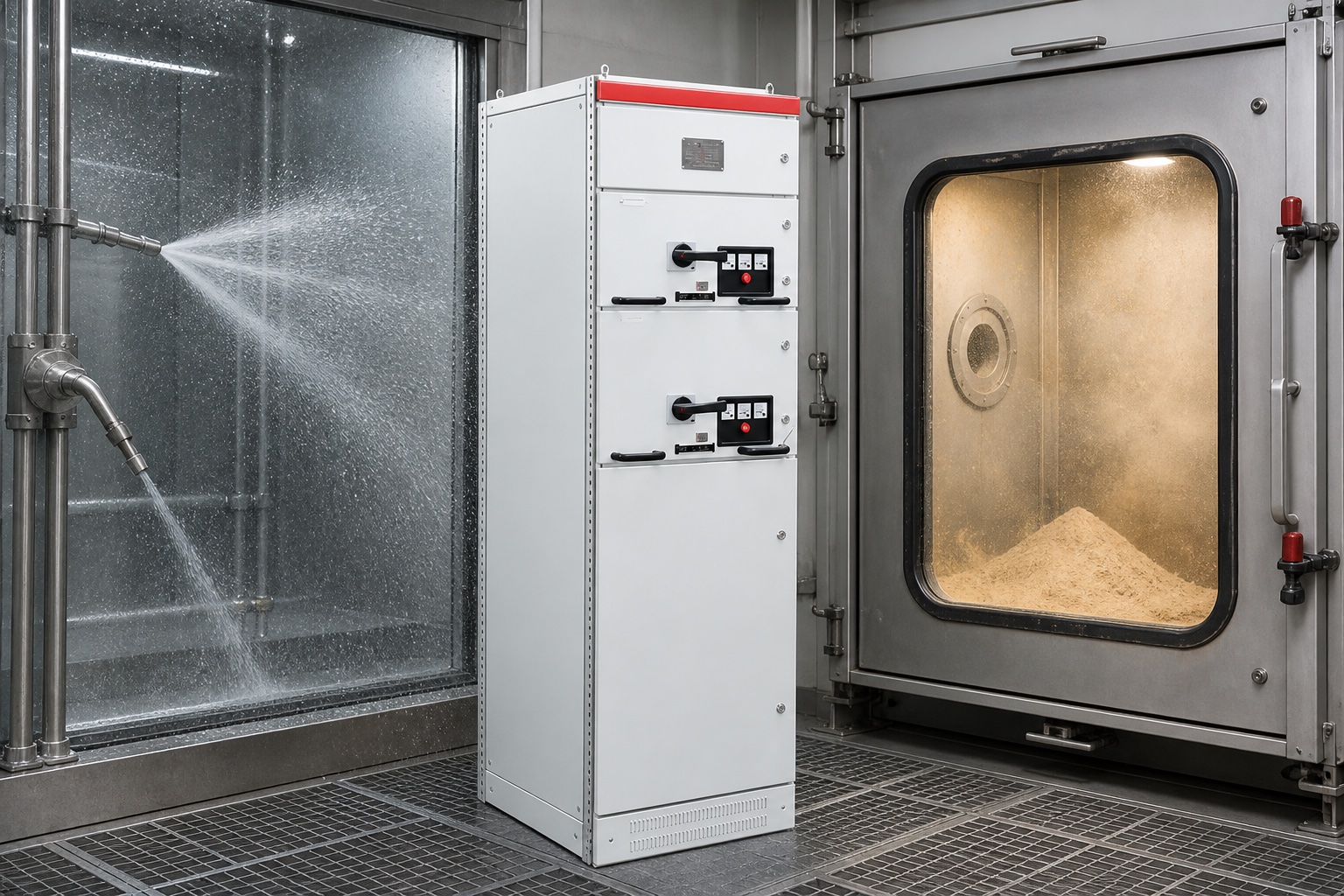
Door seals, vents, cable entries, heaters, and room conditions determine whether the enclosure keeps contaminants away from insulation.
Mechanical and electrical checks
Breakers and switching devices
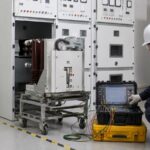
Exercise mechanisms only under the approved procedure. Inspect linkages, springs, latches, rollers, shutters, racking screws, primary disconnects, secondary plugs, and position indicators. Apply only the specified lubricant, at the specified locations and quantity. Excess or incompatible grease can collect dirt and slow mechanisms.
Connections and insulation
Do not “torque everything” automatically. Repeated tightening can damage hardware and does not substitute for joint inspection. Follow the manufacturer’s torque and joint-maintenance instructions. Electrical test selection depends on voltage class and insulation system; compare results with baseline, phase patterns, and environmental conditions.
Protection and trip chain
Confirm relay settings against the approved coordination study before testing. Secondary or primary injection may verify different portions of the protection chain. A complete functional test proves the intended relay output, lockout logic, breaker trip coil, auxiliary contacts, alarms, and supervisory signals without leaving test blocks or disabled functions behind.
Online condition checks
Thermography under representative load can identify phase imbalance and resistive joints. Partial-discharge monitoring may support medium-voltage insulation assessment when correctly applied. Environmental sensors can expose condensation. Breaker counters, coil-current signatures, and relay event records provide operational evidence. None removes the need for safe de-energized maintenance where the equipment condition and manufacturer require it.
Online inspection must not encourage unsafe access. Keep doors and covers in their normal secure condition unless the equipment and safety program provide a rated viewing method.
Common maintenance failures
Skipping the as-found condition and losing diagnostic evidence.
Using a fixed interval without considering duty, environment, or criticality.
Cleaning contamination but not repairing water entry or failed heaters.
Changing relay settings during testing without controlled approval.
Lubricating unspecified points or mixing incompatible products.
Testing individual components but not the complete trip and alarm chain.
Closing the outage without an independent tool, ground, cover, and interlock check.
Restoration and quality record
Before energization, verify every temporary ground, lead, jumper, test plug, tool, and material is removed; all barriers and covers are restored; shutters and interlocks work; breakers are in the required position; relay settings are approved; control power is normal; and remote/local selections match the switching plan. Use independent inspection for critical steps.
The final report should contain asset IDs, date, operating context, safety document references, as-found condition, test equipment and calibration, results, tolerances and sources, work performed, replacement parts, unresolved defects, as-left condition, settings files, photographs, and approvals. Trend comparable readings rather than treating each report as an isolated certificate.
Defect prioritization after the outage
Classify findings by consequence and required response. Conditions compromising insulation, interrupting capability, protection, interlocking, grounding, enclosure integrity, or safe operation may prevent return to service until engineering disposition. Other findings may permit controlled operation only with a deadline, monitoring method, operating restriction, and named owner. Cosmetic observations should still be recorded when they help track corrosion or water ingress.
A deferred defect needs more than a note. Define the technical basis, affected feeder, risk controls, required part or action, target date, and trigger for immediate shutdown. Review open defects before every subsequent operation or maintenance window.
Replacement parts and obsolescence
Verify that replacement coils, relays, breakers, fuses, shutters, and control devices are electrically and mechanically compatible. Similar appearance is not proof of rating. Changes affecting fault duty, protection logic, internal-arc performance, or type-tested construction require engineering review.
Maintain controlled backups of relay settings, firmware, logic, and communication configurations. Record the as-left revision so a later device replacement does not silently restore obsolete protection.
This independent educational overview introduces a maintenance sequence. The equipment manual and site procedure take precedence.
Kabul sınırı: A satisfactory maintenance visit means the agreed scope has been completed, results meet their stated basis, defects have a formal disposition, and the lineup has passed restoration checks. It does not guarantee indefinite future performance. Operating staff should continue monitoring alarms, temperature, environment, breaker operations, and protection events, and should reopen the maintenance decision when new evidence changes the risk.
Review the next interval after faults, abnormal operations, flooding, contamination, overheating, or major system changes rather than waiting automatically for the original calendar date.
Close every maintenance package with an operations handover that identifies changed positions, settings, limitations, alarms, and follow-up responsibilities.
Switchgear preventive maintenance FAQ
How often should switchgear be maintained?
There is no universal interval. Use manufacturer guidance, condition, environment, operation count, fault exposure, criticality, and the governing maintenance standard.
Can infrared scanning replace an outage?
No. It can reveal loaded surface temperature patterns but cannot fully inspect mechanisms, hidden insulation, contacts, interlocks, or the trip chain.
Should every bolted joint be re-torqued?
Not automatically. Follow manufacturer instructions; unnecessary repeated tightening can damage joints and hardware.
What is the most important maintenance record?
The complete as-found and as-left record with comparable measurements, settings, defects, corrective actions, and restoration evidence is more useful than a simple pass label.
Can maintenance be done with adjacent sections energized?
Only under an approved risk assessment, boundaries, equipment design, and electrical-safety procedure. The preferred condition for intrusive work is de-energized and safely isolated.
Shenheng Elektrik, müşterilerinin güvenli, verimli ve sürdürülebilir güç yönetimi elde etmesini sağlayarak, güç ekipmanı çözümlerinde küresel bir lider olmayı taahhüt eder.

 Shenheng Elektrik Ekipmanları Ticaret Limited Şirketi.