Компания Shenheng Power с 2001 года является надежным производителем оборудования для передачи и распределения электроэнергии, поставляя надежные электротехнические решения по всему миру.
Опираясь на комплексную систему послепродажного обслуживания, мы предоставляем экспертные технические консультации, рекомендации по продукции и гибкие услуги OEM и ODM для ваших проектов.
Компания Shenheng Power с 2001 года является надежным производителем оборудования для передачи и распределения электроэнергии, поставляя надежные электротехнические решения по всему миру.
A bus coupler panel connects defined bus sections or bus systems under an approved operating arrangement. It can support transfer, maintenance and supply continuity, but closing the coupler may change fault levels, source paralleling and protection boundaries. Selection therefore needs the actual single-line diagram, normal open or closed philosophy, transfer requirements and interlock logic. A bus coupler is not simply an extra feeder breaker. Its ratings, CT locations, protection functions, synchronization requirements where applicable and failure response must be coordinated with the whole switchgear lineup.
Define the role on the single-line diagram
Identify the bus sections, incoming supplies and loads on either side of the coupler. State whether the normal arrangement keeps the sections separated or connected. Describe maintenance and emergency configurations as well as normal operation, because those alternatives can create the most demanding duties.
Do not confuse a bus-section coupler with every possible bus-transfer or bypass arrangement. Different single-line schemes use different devices and operating sequences. Name the function and show it on the project drawing so bidders do not interpret the same term differently.
The single versus double bus substation guide provides a useful upstream topic for comparing schemes. The actual coupler decision should then use the installed or proposed layout, including source characteristics and the owner’s transfer philosophy.
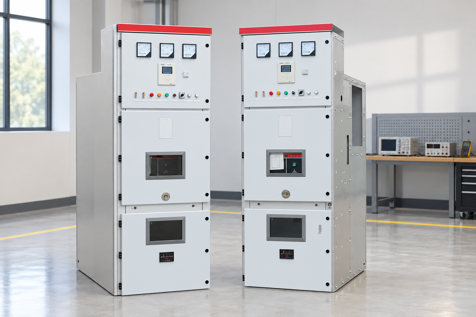
Review source capacity, transfer logic and protection boundaries. Reference-based illustration.
Operating philosophy comparison
Operating case
Main purpose
Questions before operation
Required design evidence
Normally open coupler
Keep sections separated
Can one source carry transferred load?
Capacity and transfer assessment
Normally closed coupler
Operate connected bus sections
What combined fault duty applies?
Fault study and protection design
Dead-bus transfer
Restore a section from another source
Is the failed supply isolated and the bus state verified?
Transfer logic and permissives
Live-source connection
Connect two energized systems where permitted
Are paralleling and synchronization acceptable?
Source agreement and synchronization scheme
Maintenance configuration
Isolate equipment while serving loads
Which zones and interlocks change?
Approved operating diagram
Coupler failure
Address a device that fails to clear or operate
Which backup actions protect the system?
Breaker-failure and backup-protection review
The table identifies engineering conditions, not a switching sequence. IIT Roorkee’s power-system protection course includes busbar protection as a system topic. The project settings and logic require a qualified protection design for the specific scheme.
Normal-open does not mean the coupler has a light duty
A normally open device may still need to carry the transferred load and withstand the fault duty associated with the emergency arrangement. Its infrequent operation does not justify selecting ratings from normal current alone. Include every permitted operating case in the equipment assessment.
Check the capacity of the source that supplies both sections during transfer. The transformer, incoming cable, incomer, busbars and coupler all form part of that path. A coupler with adequate current rating cannot compensate for an overloaded incoming circuit or transformer.
Review load shedding if the surviving source cannot support the entire demand. Identify which loads may transfer automatically and which require operator decisions. The owner should understand the service consequences before procurement, rather than discovering during an outage that the emergency configuration was assumed to carry everything.
Source paralleling and synchronization
Closing between energized sections may parallel sources. That can affect circulating current, fault level, operating agreements and stability. Determine whether paralleling is permitted, for how long and under which conditions. A generic synchronization relay specification does not authorize utility paralleling.
Where synchronization is required, identify the measured voltages, frequency and phase conditions used by the approved scheme. Review VT selection, fuse or circuit-failure supervision, permissive logic and timeout behavior. The settings belong to the actual source and operating agreement; there is no universal threshold appropriate to every project.
A transfer scheme should state whether it is open transition, closed transition or another approved arrangement. It must also define what happens when the expected bus state cannot be confirmed. Avoid logic that closes the coupler merely because one voltage indication disappears without evaluating the failure mode of that indication.
Fault levels and equipment ratings
A connected-bus arrangement can expose equipment to contributions from more than one source. Evaluate the permitted configurations using the fault study and compare them with the lineup’s ratings. The coupler can change the duty seen by incomers and outgoing feeders as well as by its own breaker.
Use consistent definitions for making duty, breaking duty and short-time withstand. These quantities answer different questions. The breaking versus making capacity guide helps distinguish them, but the final selection requires the actual prospective current and clearing conditions.
Check the entire assembly, including busbar joints, CTs and interconnections. A breaker data sheet is not proof that the complete panel or lineup meets the same duty. Request the reports and configuration information that support the offered assembly.
CT locations and protection zones
CT positions determine how current is measured and how protection zones meet or overlap. A coupler can sit at the boundary between bus sections, so the protection designer must account for the breaker and the connections around it. An unexamined gap can leave a section protected only by slower backup functions.
Describe the busbar scheme, coupler CT arrangement and any zone-selection logic. Identify how device positions affect the measurements assigned to each zone. Confirm polarity, ratio, saturation considerations and wiring against the protection drawings.
Используйте substation protection-zone guide to organize the boundary review. A diagram should show the intended coverage explicitly rather than rely on a statement that both bus sections have protection.
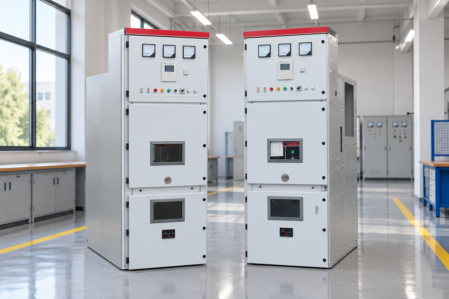
Commission the complete scheme, including blocked operations and failures. Reference-based illustration.
Interlocks and transfer controls
Define which combinations of incomer and coupler positions are permitted. Some projects prevent simultaneous closure of two incomers and a coupler; other projects permit particular parallel states. The correct logic comes from the operating philosophy, not a generic assumption about a three-breaker arrangement.
Document local, remote and automatic modes. Review control power, auxiliary contacts, selectors, alarms, command timeout and repeated-command behavior. A transfer sequence must stop safely when a required operation or indication fails. It should not silently continue because a later step appears possible.
OSHA’s work-practice reference is relevant to the distinction between control logic and verified isolation. Interlocks support an operating scheme, but they do not replace the owner’s safe-work procedures for maintenance or investigation.
Commissioning the complete scheme
Prepare a test matrix with starting states, commands, expected actions and indications. Include successful transfer, blocked transfer, loss of control supply, failed breaker operation, missing voltage input and inconsistent position feedback. The purpose is to verify the whole sequence, not just demonstrate that the coupler can close.
Validate the protection functions and settings through the approved test plan. Confirm CT circuits, trip paths, intertrips, backup actions and alarm destinations. If the scheme uses communications, identify their failure behavior and ensure that the relevant tests address it.
Record the final settings, logic revision and drawings at commissioning. A factory-tested program that has been modified on site needs the relevant tests repeated. Retain the event recordings and acceptance results so future investigations can compare actual behavior with the approved baseline.
Maintenance and restoration planning
Identify what must be isolated to service the coupler, its CTs, control circuits or adjacent bus connections. Review whether access requires an outage of one or both sections. The maintenance method should align with the physical compartment arrangement and the site’s safety rules.
Inspect mechanisms, indications, control supply and accessible connections according to the manufacturer and owner program. If a transfer fails, collect alarms and event data before resetting or changing logic. A failed indication and a failed mechanical operation can produce similar operator symptoms but require different repairs.
Plan spare devices and support for the transfer controls as well as the primary breaker. A coupler may be mechanically serviceable while its automatic-transfer function is unavailable due to an obsolete control component. Document the supported repair and replacement path for the whole scheme.
Inquiry information for the panel supplier
For a medium-voltage switchgear inquiry, provide the single-line diagram, source data, required ratings, CT scheme, bus arrangement, transfer philosophy and communication requirements. Request the exact panel function rather than assuming that every model family includes the needed coupler configuration.
Ask for assembly drawings, rating evidence, CT and VT details, interlock matrix, control logic, protection interfaces and maintenance instructions. Identify any site-supplied relays, VTs or automation that participate in the scheme. Require exclusions and deviations to be stated before comparing quotations.
At acceptance, compare the final equipment and logic with the approved operating cases. The useful result is a coupler arrangement whose normal, emergency and failure behavior is understood and verified. A cabinet label saying “bus coupler” does not establish that outcome.
Further learning
Further learning: Lecture 31 Protection of Busbars — IIT Roorkee July 2018. This educational video supports the topic; it is not a product demonstration or an operating authorization. Открыть видео на YouTube.
Часто задаваемые вопросы
Should a bus coupler normally be open or closed?
That depends on the network and operating philosophy. Evaluate fault levels, source capacity, reliability and protection for all permitted states before deciding.
Can a coupler close between two live sources?
Only where the source agreements and engineered scheme permit it. Synchronization, fault duty and operating conditions must be established for the actual project.
Does a three-breaker interlock always prohibit all three breakers being closed?
No universal logic applies. Many schemes impose that restriction, while other approved designs permit particular parallel states. Use the documented project matrix.
What is the most important commissioning check?
Verify the complete transfer and protection behavior, including prohibited states and failures. Testing the breaker alone does not verify the system function.
Компания Shenheng Electric Power стремится стать мировым лидером в области решений для энергетического оборудования, помогая клиентам обеспечивать безопасное, эффективное и экологичное управление электроснабжением.

 Шэньхэн Силовое Оборудование Ко., Лтд.