Desde 2001, a Shenheng Power tem sido um fabricante de confiança de equipamento de transmissão e distribuição de energia, fornecendo soluções elétricas fiáveis a nível global.
Apoiados por um sistema pós-venda completo, fornecemos consultoria técnica especializada, orientação de produtos e serviços flexíveis de OEM e ODM para os seus projetos.
Desde 2001, a Shenheng Power tem sido um fabricante de confiança de equipamento de transmissão e distribuição de energia, fornecendo soluções elétricas fiáveis a nível global.
Transformer Noise Limits, Causes and Reduction Methods
Release Time: 2026-10-17
Transformer noise reduction starts with identifying whether an oil immersed transformer’s sound comes mainly from the core, load related vibration, cooling equipment, or its mounting and surroundings. Measure the operating condition before choosing a remedy. A transformer sound rating, a reading beside the tank, and noise at a property boundary describe different things. None should be substituted for another. This guide focuses on equipment diagnosis, procurement and corrective work for oil filled units; use a separate environmental assessment for community limits and site planning.
Define the sound problem before buying a solution
Begin with the complaint and the equipment identity. Is the concern a new rattle, a steady hum that has always been present, a cooling fan starting at night, or vibration reaching an occupied structure? Each question points toward different measurements. Record the transformer serial number, supply frequency, tap position, loading, cooling stage and the time the sound became noticeable. Include changes in nearby equipment or the building.
An audible change deserves investigation, but sound alone cannot identify an internal fault or prove a transformer safe. Follow the site’s escalation procedure if noise accompanies protection operation, smoke, leakage, abnormal temperature or other distress. Keep observers outside the equipment’s controlled area. Opening an enclosure, touching a tank or changing supports is not part of an informal listening check.
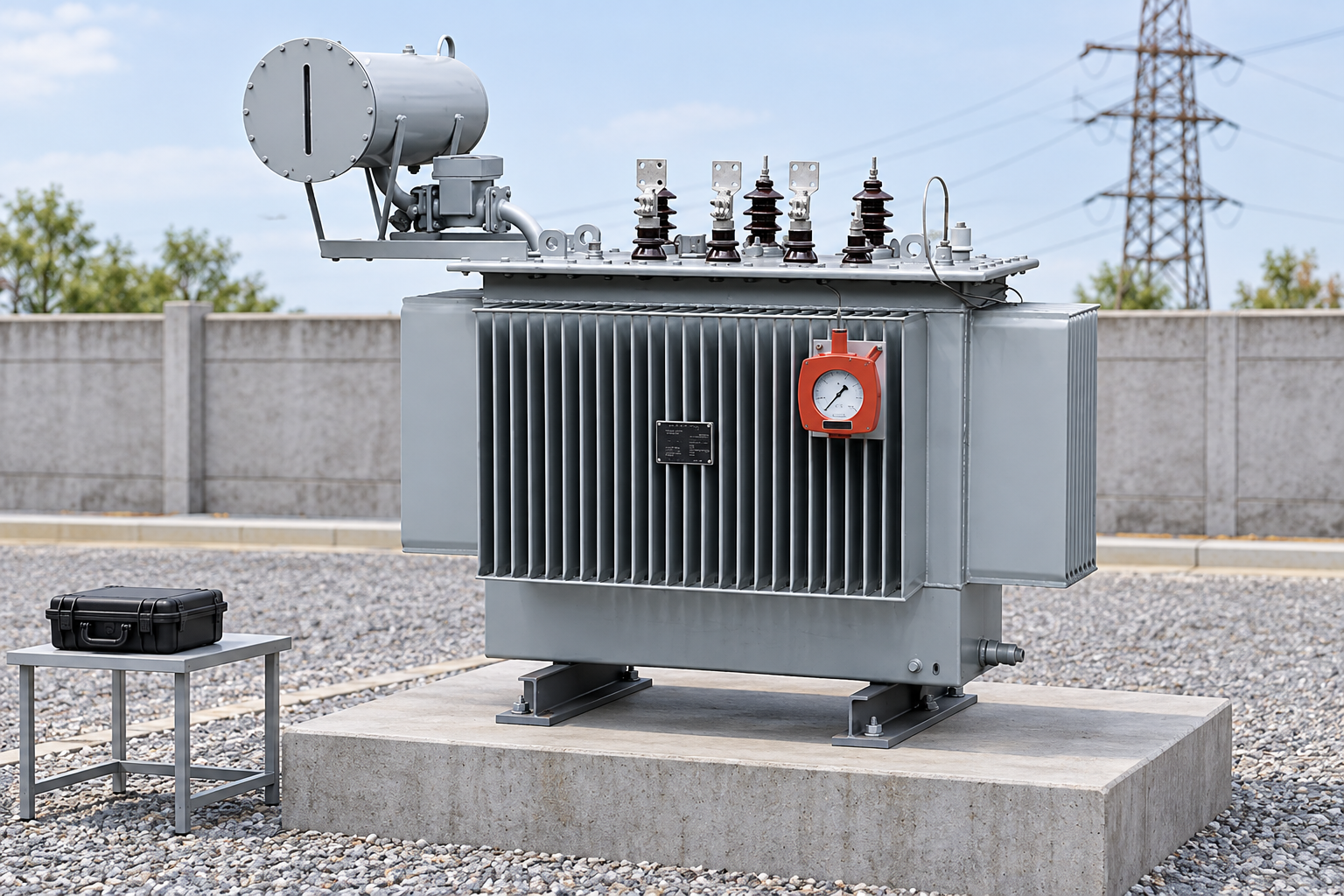
For the relevant equipment family, review the oil immersed power transformer product and obtain its approved drawings and test documents. Photographs establish product context; they do not establish a guaranteed sound level or the installed accessory arrangement.
Separate core, winding and auxiliary sources
Magnetostriction means that magnetic material changes shape when magnetized. Ghent University’s explanation identifies its contribution to vibration and noise in transformer cores. A periodic core excitation can therefore produce sound even when useful load is small. This explains why unloading a unit does not necessarily eliminate its hum.
Winding forces and structural response can contribute as loading changes. Fans, pumps and their supports can introduce additional components when those accessories are fitted. A panel or pipe can transmit or amplify vibration without being the original excitation source. Avoid assuming that the loudest surface is the component that needs replacement.
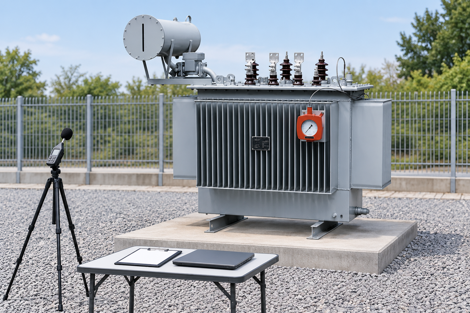
Compare recordings with load and cooling information rather than judging a single audio clip. A phone recording may help document a change, but its automatic processing and microphone response make it unsuitable as the sole acceptance measurement. A qualified survey should use appropriate instruments, documented settings and consistent positions.
Review support and vibration transmission paths using approved drawings. Reference-based illustration.
Build a repeatable diagnostic baseline
Choose measurement positions that can be reached safely and reproduced later. Mark them on a controlled drawing, describe the microphone height and orientation, and record the instrument and calibration checks. Note walls, fences, reflective surfaces and other operating machinery. Weather and background noise matter for outdoor readings; a windy or busy measurement period may obscure the source being investigated.
Use multiple operating snapshots when practicable: similar supply conditions at different loads, cooling equipment off and on where normal operation permits, and a representative stable condition. Changes to cooling or electrical operation must be authorized by the operator. Do not stop a necessary fan solely to make a noise reading look better.
Where vibration transmission is suspected, coordinate an instrumented assessment with the equipment manufacturer and a specialist. Sensor placement, attachment and access must be suitable for the equipment and work permit. An acoustic survey should not become an unauthorized intervention on energized plant.
Match the symptom to the evidence
The following table is a diagnostic planning aid, not a fault diagnosis or a set of sound limits. It uses the distinction between magnetic excitation, mechanical transmission and auxiliary sources discussed in the university material above and the maintenance guidance linked below.
Observed pattern
Evidence to collect
Sensible next decision
Avoid this shortcut
Steady tonal hum at light load
Voltage, frequency, tap position and repeatable sound readings
Ask the manufacturer to compare the operating point with the sound test basis
Assuming no load means no core noise
Sound changes with load
Load records, spectra and cooling state
Separate load response from auxiliary operation
Calling every increase a loose core
Noise starts with a fan or pump
Accessory identity, start times and condition records
Review the accessory and its supports under an approved maintenance plan
Disabling required cooling
Rattle near a cover or fitting
Safe external observations and vibration assessment
Plan inspection during an appropriate outage
Tightening unknown fasteners while energized
Hum prominent in an adjacent room
Foundation, structural and service connection paths
Review transmission paths before adding an outdoor wall
Treating all received sound as airborne
New noise with other warning signs
Alarm history, temperatures and protection events
Follow the operator’s abnormal condition procedure
Using an acoustic fix to conceal a developing fault
Check operating conditions before mechanical changes
Compare the actual supply and tap arrangement with the approved operating envelope. The relationship between applied voltage and frequency influences core excitation, but a sound complaint is not sufficient evidence to change taps or supply settings. Have the responsible electrical engineer review measurements and manufacturer guidance before altering the operating point.
Review loading and its waveform where the application warrants it. A change in production equipment may change the electrical environment as well as the cooling duty. Establish whether the noise change coincides with a load change, a fan stage or a network event. This keeps the investigation focused and prevents replacing mechanical parts when the operating cause remains.
For fluid filled equipment, cooling surfaces and accessory operation also belong in the condition review. Follow the manufacturer’s maintenance instructions and the Bureau of Reclamation transformer maintenance guidance, recognizing that this is general guidance rather than an instruction for a specific supplied unit.
Review the foundation and transmission paths
A transformer can transmit vibration through its supports and into a floor or adjoining structure. Rigid service connections can provide additional paths. Map the actual supports, rails, anchorage and connections before selecting any isolation arrangement. Record whether the present installation matches the approved drawing and whether transport restraints have been handled as instructed by the manufacturer.
An isolator is an engineered support component, not a universal pad to slide under heavy equipment. Its selection affects load distribution, movement, anchorage, seismic restraint and service connections. Never lift or loosen a transformer to try an improvised isolation material. A proposed modification needs mechanical, electrical and manufacturer review, followed by an approved outage and lifting plan where applicable.
Likewise, do not loosen core clamps or structural fasteners in pursuit of a quieter sound. Internal adjustments can affect equipment integrity. If the evidence points inside the tank, involve the manufacturer and preserve the investigation records rather than attempting a generic field remedy.
Choose barriers and enclosures with cooling in mind
An acoustic barrier may help with a particular propagation path, but it will not automatically resolve structure borne transmission. Its benefit depends on source and receiver geometry and frequency content. A partial wall can also redirect sound toward a different receiver. Refer broader receiver questions to the substation noise assessment guide.
A close enclosure introduces additional design questions: heat rejection, inspection access, fire protection interfaces, drainage, electrical distances and maintenance removal routes. Covering radiator surfaces with sound absorbing material is not a legitimate substitute for an engineered solution. Confirm thermal performance and access before committing to construction.
For indoor dry type equipment, use the separate dry type transformer noise guide. Resin windings, enclosure ventilation and indoor installation constraints require their own assessment. A solution designed for that equipment should not be transferred unchanged to an oil filled conservator unit.
Compare operating conditions and documented survey results. Reference-based illustration.
Specify a sound requirement that can be tested
A purchase specification should identify the applicable sound measurement standard and edition, the reported quantity, the operating condition, included accessories and the acceptance process. Ask whether the offered result is measured, guaranteed or estimated, and what tolerances or corrections apply. Request the test report for the ordered configuration rather than an unrelated brochure value.
Do not specify one unexplained decibel number. Sound pressure and sound power are different quantities; weighting, measurement surface and cooling condition affect interpretation. An equipment test also cannot demonstrate compliance at a distant bedroom or property boundary without a propagation assessment. Define both equipment acceptance and any separate site obligation in the contract.
For a replacement unit, provide installation drawings, receiver concerns, permitted dimensions, connection constraints and planned cooling duty. Early coordination gives suppliers a realistic opportunity to address sound in the equipment design instead of relying on an expensive enclosure after delivery.
Verify the result and retain the records
Set the verification method before the corrective work. Repeat the baseline positions and instrument settings at a comparable operating condition. Explain material differences in load, background noise or cooling state; a lower reading on a quiet day is not automatically proof that the modification achieved its intended effect. Keep the original and revised data together.
Inspect the installation after modification for unintended consequences, including blocked cooling, inaccessible fittings, strained connections or obstructed maintenance routes. Confirm that any support or enclosure changes have their required approvals. Add the new inspection points to the maintenance plan and retain the drawings with the equipment record.
If leakage or accessory concerns emerge during the survey, handle them through the relevant condition assessment rather than acoustic treatment. The transformer oil leak guide explains that separate investigation. A quieter installation is useful only when the electrical and mechanical condition remains acceptable.
Further learning: why the magnetic core makes sound
The teaching video below explains magnetostriction. It supports understanding of the source mechanism; it does not provide a sound guarantee for the illustrated transformer or authorize field adjustments.
Further learning: Magnetostriction in Transformers Explained | Why do transformers make a humming noise? | MADE EASY — MADE EASY. Educational background; this is not an operating authorization. Abrir o vídeo no YouTube.
Perguntas Frequentes
Is there one acceptable noise limit for every transformer?
No. An equipment requirement depends on its specification and test basis, while site limits depend on the applicable jurisdiction and receiving location. Define the quantity, operating condition and assessment method before comparing a measured value with a requirement.
Does transformer hum always mean a fault?
No. Magnetic excitation can produce normal sound. A new or unusual noise, especially with alarms, leakage or temperature changes, needs investigation under the operator’s procedures. Sound alone cannot prove either a fault or safe operation.
Can rubber pads solve transformer vibration?
Only an engineered support arrangement should be considered. Load capacity, movement, anchorage and electrical connections must remain acceptable. Improvised pads or unauthorized lifting can create additional problems and should not be used as a trial remedy.
What should a noise reduction enquiry include?
Include equipment identity, drawings, operating records, sound and vibration measurements, receiver concerns, cooling configuration and the desired acceptance method. Describe previous changes and the permitted installation envelope so the proposed remedy addresses a documented source and path.
A Shenheng Electric Power está empenhada em tornar-se líder global em soluções de equipamentos elétricos, ajudando os clientes a alcançar uma gestão de energia segura, eficiente e sustentável.
Se tiver alguma dúvida ou precisar de ajuda, não hesite em contactar a nossa equipa.
N.º 168, Estrada South Sixth de Punan, Zona de Desenvolvimento Económico de Yueqing, Cidade de Yueqing, Cidade de Wenzhou, Província de Zhejiang, China

 Shenheng Power Equipment Co., Ltd.