Desde 2001, a Shenheng Power tem sido um fabricante de confiança de equipamento de transmissão e distribuição de energia, fornecendo soluções elétricas fiáveis a nível global.
Apoiados por um sistema pós-venda completo, fornecemos consultoria técnica especializada, orientação de produtos e serviços flexíveis de OEM e ODM para os seus projetos.
Desde 2001, a Shenheng Power tem sido um fabricante de confiança de equipamento de transmissão e distribuição de energia, fornecendo soluções elétricas fiáveis a nível global.
Switchgear room clearance must satisfy the applicable electrical rules and the actual equipment’s operation, maintenance and removal requirements. Start with voltage to ground, access to energized parts, the surfaces facing the equipment and the adopted code edition. Then overlay doors, breaker withdrawal, cable access, pressure relief routes and exits using approved drawings. A single generic aisle dimension cannot establish a compliant room. This guide addresses room planning for switchgear; internal insulation distances and transformer installation spacing are separate subjects.
Establish the governing rules and equipment identity
Record the installation country, authority having jurisdiction, project standards, nominal system voltage, voltage to ground and equipment construction. The governing requirements may differ between low and medium voltage installations and between public access areas and controlled electrical rooms. Do not transfer a diagram from another jurisdiction without checking its applicability.
Use the ordered cabinet arrangement rather than a representative catalog sketch. The KYN28 switchgear product family provides a starting point for an enquiry. Obtain the supplier’s approved overall dimensions, access instructions, door swings, withdrawal envelope and installation manual for the specific arrangement before fixing the building dimensions.
Keep an assumptions register when the order is incomplete. Label any room layout based on preliminary dimensions as provisional, identify the missing inputs and assign a review date. This prevents an early architectural outline becoming an unchangeable requirement before the electrical design is known.
Distinguish the spaces that the room must provide
Working space supports access for examination, adjustment, servicing or maintenance under the conditions addressed by the governing rules. It is different from a transport route for heavy components and different again from space dedicated to electrical equipment. Each must be checked on its own basis before they are coordinated.
Maintenance access includes the space needed to open doors, remove covers, reach cable compartments and use approved tools. A withdrawable circuit breaker may need a handling truck and room for turning or staging. That envelope can be greater than a statutory working depth and cannot be inferred from the width of a closed cabinet.
For internal air distances between conductors and grounded metal, consult the equipment design and the separate switchgear creepage and clearance guide. Increasing a room aisle does not correct an inadequate internal insulation arrangement, and an insulation test does not demonstrate that the room has adequate exits.
Determine the electrical working space from the correct inputs
Rules commonly distinguish voltage and the conditions on opposite sides of the workspace. For example, California’s high voltage workspace provisions explicitly identify voltage to ground and different facing conditions, and address door opening and access. Their dimensional table applies within that regulatory context; it is not a worldwide switchgear room schedule.
List the relevant inputs on the drawing instead of adding a dimension without explanation. Identify which face requires access, whether parts can be exposed during the relevant activity, the opposite surface and the rule used. Verify the point from which a distance is measured. The front of an enclosure and an internal live part are not interchangeable reference planes.
A layout satisfying a minimum dimension does not authorize energized work. Deenergization, isolation, verification and the site’s work controls remain separate requirements. The DOE Electrical Safety Handbook provides safety context; the adopted rules, current facility procedures and equipment instructions control the actual task.
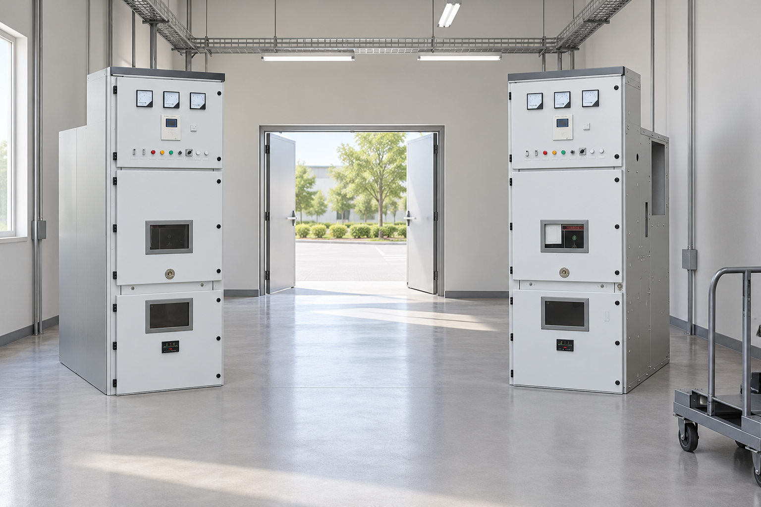
Retain working access and a separate route for maintenance movements. Reference-based illustration.
Build an access schedule before drawing the final room
The table below is a coordination checklist based on the distinction between regulatory working access and equipment service needs. It deliberately gives no universal clearance values. The designer must derive dimensions from the applicable rules and approved equipment information.
Space or interface
Input required
Drawing check
Provas a reter
Front working area
Governing rule, voltage and facing condition
Clear depth, width and height from correct reference plane
Rule and edition, dimensioned plan
Rear service area
Supplier’s access and termination instructions
Cover removal, tools and personnel position
Approved rear access drawing
Door swing
Actual hinge arrangement and opening requirement
Door cannot trap a person or obstruct the necessary route
Door envelope on room plan
Breaker withdrawal
Breaker and handling truck dimensions
Extraction, transfer, turning and staging
Manufacturer’s handling envelope
Cable entry
Cable dimensions, bending and termination arrangement
Entry route, support and compartment access
Cable and civil interface drawing
Room exits
Applicable egress requirements and room configuration
Reachable route during relevant equipment states
Building and electrical coordination record
Pressure relief
Tested equipment configuration and supplier instructions
No incompatible obstruction in discharge path
Installation and internal arc documents
Future extension
Confirmed bus extension method and construction sequence
Reserved area can actually be used
Approved expansion concept
Resolve front and rear access deliberately
A front accessible lineup may reduce some rear service needs, but the term does not establish that every component can be installed or maintained from the front. Confirm cable connections, bus extensions, pressure relief arrangements and any rear removable parts. Obtain a written explanation of what access is required throughout the equipment life.
For rear accessible gear, draw the real service area and the route to it. Check whether end panels or structural columns restrict entry. A narrow gap that can be entered during construction may become inaccessible after cable installation. Show the completed condition, including supports and building services.
Avoid placing two equipment faces opposite one another using only the sum of door widths. The applicable electrical conditions, personnel position, normal operating arrangements and service procedure must all be reviewed. A plan should state which simultaneous activities it accommodates and which require a controlled outage or restricted area.
Check withdrawal and heavy component movement
Trace the component route from its installed position to the maintenance or loading area. Include the handling truck, wheel path, turning space, floor level changes, thresholds and door openings. Check floor loading and any lifting arrangements with the structural designer and equipment supplier.
A component can clear its compartment yet still be impossible to remove from the room. Conversely, an oversized delivery door does not prove that the breaker can be withdrawn safely while other cabinets remain in service. Keep delivery, routine maintenance and major replacement routes visible as separate drawing layers.
Use a scaled envelope or a physical mockup where the geometry is difficult. Record the agreed handling procedure and assumptions about adjacent equipment. If future extension will occupy today’s staging area, plan a replacement staging location before approving the extension.
Coordinate arc pressure relief and escape routes
Internal arc classification is tied to a tested arrangement and declared accessibility conditions. Do not assume that a room wall, low ceiling or improvised exhaust duct is compatible with that arrangement. Ask the supplier which installation conditions are necessary and how any pressure relief system interfaces with the room.
O switchgear internal arc classification guide covers equipment evidence. Room planning must also consider where people can stand and how they can leave. Keep exits and necessary paths free of storage, temporary cables and maintenance equipment under the site’s operating arrangements.
An arc resistant label is not a substitute for an arc flash assessment or safe work procedure. Coordinate the room geometry with the arc flash study inputs, protection design and operating policy. Any building change affecting equipment access or discharge routes needs renewed review.
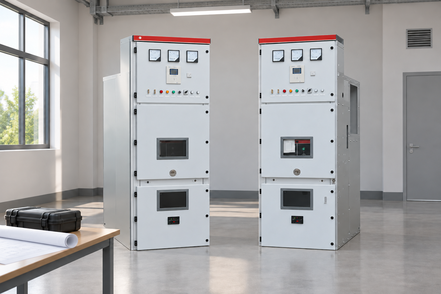
Verify the room layout against approved dimensional drawings. Reference-based illustration.
Keep cable, ventilation and building services out of conflicts
Overlay cable trenches, overhead services, doors, ventilation openings and the equipment footprint. Cable bending, termination and support requirements may dictate more space than the initial enclosure outline suggests. Do not route services through areas reserved by the applicable electrical rules without a qualified design review.
Ventilation equipment must remain serviceable without blocking electrical access. A duct or pipe added after room approval can reduce usable headroom or obstruct a pressure relief path. Review building service revisions against the controlled electrical layout, not just an architectural background drawing.
Room planning should connect with the equipment interfaces in the substation control building guide. That guide considers broader building functions; this article focuses on the switchgear access envelopes that need to be preserved within the building.
Verify the constructed room before acceptance
Measure the completed installation using the approved reference points. Check the conditions that are easy to miss on drawings: door stops, protruding handles, cable supports, thresholds, temporary storage and the position of ventilation equipment. A clear outline on a floor plan does not prove that the finished space is clear.
Demonstrate the agreed movement of a breaker or representative handling arrangement under an approved procedure. Confirm that covers and compartments can be accessed as intended. Include inspection of routes and room interfaces in the site acceptance checklist, while keeping the equipment test results and building measurements distinguishable.
Record discrepancies with their owner and disposition. Do not close a clearance issue by repainting floor lines around an obstruction. The responsible designer must assess whether the equipment, room or working arrangement needs to change and obtain the necessary approval.
Preserve the layout during operation and future work
Assign responsibility for keeping access clear. Electrical rooms should have controlled storage and maintenance arrangements that protect the required spaces. Retain the approved drawings in the facility record and use them when installing replacement equipment, new cable supports or additional building services.
A replacement cabinet with the same nominal voltage may have different access and withdrawal requirements. Review its dimensions and instructions before purchase. The practical value of a well documented room is that a later change can be assessed against explicit assumptions rather than relying on the fact that the previous equipment fitted.
Further learning: electrical working space principles
Mike Holt’s training video explains working space in the stated 2020 NEC context. Use it to understand the concepts and questions to ask; apply the edition and voltage provisions adopted for the actual project rather than transferring its examples directly to every medium voltage room.
Further learning: Working Space about Electrical Equipment [110.26, 2020 NEC] — MikeHoltNEC. Educational background; this is not an operating authorization. Abrir o vídeo no YouTube.
Perguntas Frequentes
Is one metre enough clearance in front of every switchgear lineup?
No universal dimension applies. Determine the governing electrical requirement and compare it with the ordered equipment’s operation, maintenance, withdrawal and egress needs. Keep the controlling assumptions and reference points on the approved drawing.
Can front accessible switchgear be installed against a wall?
Only if the ordered equipment and its installation instructions permit the arrangement and all applicable requirements remain satisfied. Confirm rear connections, removable parts, cooling, pressure relief and future work before accepting a wall adjacent installation.
Does a working space dimension include breaker removal?
Not necessarily. Breaker withdrawal, handling trucks, turning and staging can require additional space. Review the movement envelope separately and coordinate it with working access and the route out of the room.
What documents should accompany a room layout enquiry?
Provide the jurisdiction and code basis, system voltage information, room dimensions, exits, service routes and required maintenance activities. Request approved cabinet dimensions, access and withdrawal envelopes, cable interfaces and pressure relief instructions for the offered configuration.
A Shenheng Electric Power está empenhada em tornar-se líder global em soluções de equipamentos elétricos, ajudando os clientes a alcançar uma gestão de energia segura, eficiente e sustentável.
Se tiver alguma dúvida ou precisar de ajuda, não hesite em contactar a nossa equipa.
N.º 168, Estrada South Sixth de Punan, Zona de Desenvolvimento Económico de Yueqing, Cidade de Yueqing, Cidade de Wenzhou, Província de Zhejiang, China

 Shenheng Power Equipment Co., Ltd.



![Working Space about Electrical Equipment [110.26, 2020 NEC]](https://shenhengglobal.com/wp-content/cache/flying-press/d4474eac2f9547582c22661c90a67366.jpg)