Od 2001 roku Shenheng Power jest zaufanym producentem sprzętu do przesyłu i dystrybucji energii elektrycznej, dostarczającym niezawodne rozwiązania elektryczne na całym świecie.
Dzięki kompleksowemu systemowi obsługi posprzedażowej zapewniamy fachowe doradztwo techniczne, wskazówki dotyczące produktów oraz elastyczne usługi OEM i ODM dla Państwa projektów.
Od 2001 roku Shenheng Power jest zaufanym producentem sprzętu do przesyłu i dystrybucji energii elektrycznej, dostarczającym niezawodne rozwiązania elektryczne na całym świecie.
Form 1, Form 2, Form 3 and Form 4 Separation in LV Switchgear
Release Time: 2026-10-13
Switchgear form of separation describes how a low voltage assembly internally separates busbars, functional units and external conductor terminals. Form numbers organize those arrangements; they do not alone prove internal arc performance, service continuity or permission for live work. Buyers should choose an arrangement by reviewing the maintenance tasks, isolation boundaries, cable access and replacement procedure for the actual assembly. The supplier’s drawings and documented design must then show what the offered form means for the delivered equipment. This guide explains that procurement decision for low voltage power switchgear and controlgear assemblies.
What internal separation is trying to achieve
An assembly combines incoming supplies, busbars, outgoing circuits and their connections within an enclosure or related construction. Internal separation establishes boundaries among selected parts. The practical review concerns what remains accessible when a particular compartment is opened, how circuit terminals are arranged and what the maintenance task requires.
Read form designations alongside the applicable standard and supplier drawings. The IEC 61439-2 publication record identifies the power assembly standard and notes clarification of internal separation requirements in its 2020 edition. The public record is a scope and edition reference, not the complete definition or acceptance procedure for every arrangement.
The BEAMA Guide to Forms of Separation provides industry explanations and illustrations for reviewing the distinctions. Use those definitions and the applicable adopted standard during design review. The purchasing checklist below translates the topic into questions for a particular project; it does not replace their full requirements.
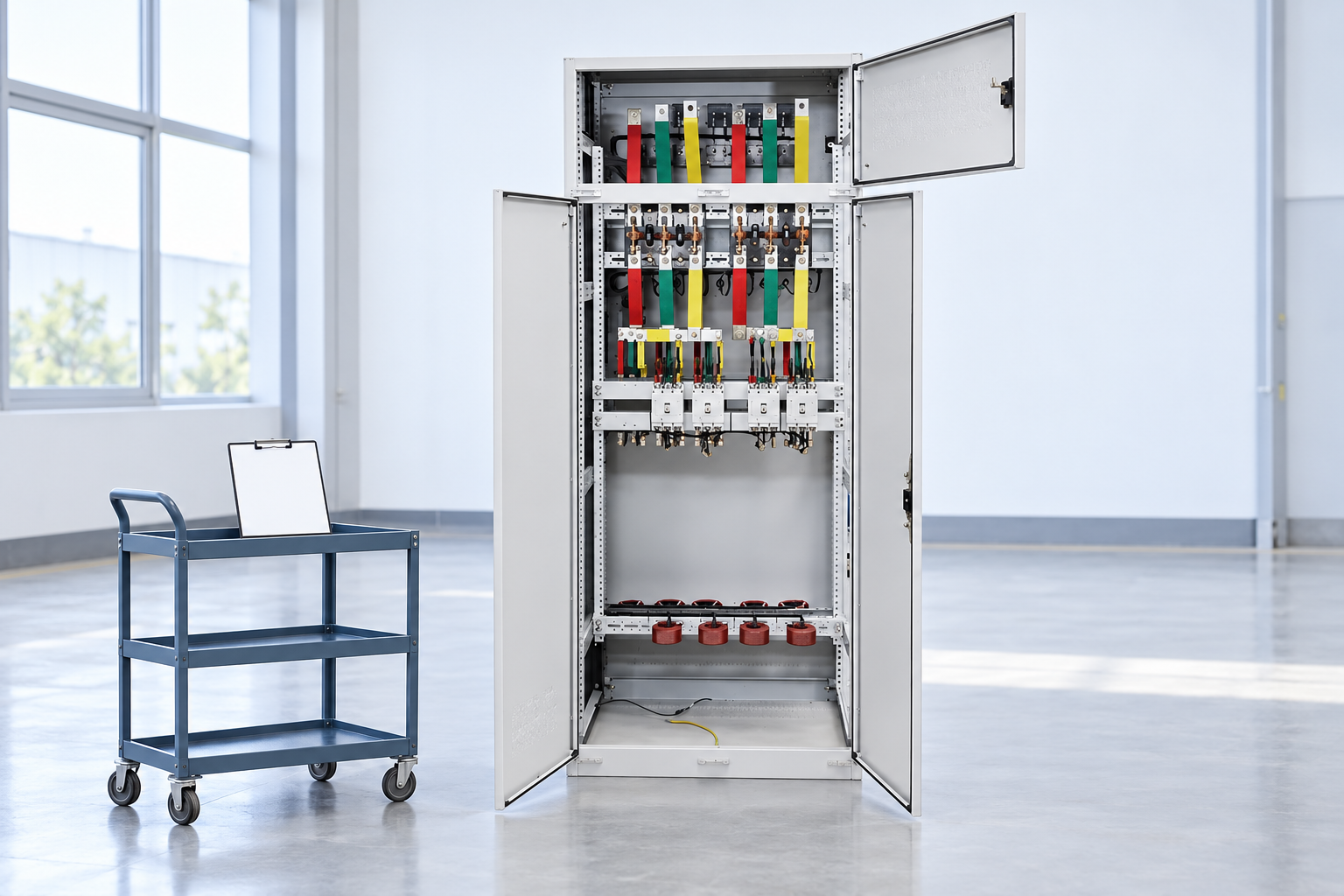
Review busbar and terminal boundaries in approved drawings. Reference-based illustration.
The broad distinction between Forms 1, 2, 3 and 4
At a broad level, Form 1 provides no internal separation. Form 2 separates busbars from functional units. Form 3 also separates functional units from one another. Form 4 adds separation of the terminals associated with an individual functional unit from those associated with other units. The letter suffixes address terminal and busbar relationships; review their exact definitions against the approved drawings.
These short descriptions are orientation only. They do not establish compartment dimensions, acceptable access, replacement methods or a rating for a particular product. Some important differences become apparent only when the cable arrangement and isolation sequence are reviewed together.
Do not turn the form number into an unconditional quality ranking. A project may need a particular arrangement because of its maintenance tasks; another may reasonably select a simpler arrangement with a different outage plan. The decision must still satisfy applicable requirements and the installation’s risk assessment.
Start with the task, then select the arrangement
Describe the maintenance activities expected over the assembly’s life. Examples include connecting an additional outgoing cable, replacing a protective device, inspecting a termination or removing a complete functional unit. Each activity has different access and isolation needs. “Maintenance without interruption” is too vague unless it names the circuits allowed to remain in service and the conditions required.
For each task, draw or describe the route by which a worker reaches the relevant part. Identify the barriers, covers, terminals and adjacent circuits encountered. Then establish the approved deenergized work procedure. A form designation cannot replace that analysis or the local electrical safety rules.
Ask the supplier to demonstrate how the proposed construction supports the agreed task. Evidence can include drawings, compartment views, cable termination arrangements and the manufacturer’s replacement instructions. A general photograph of a similar cabinet is useful for orientation but does not resolve the offered variant’s access or isolation boundaries.
A procurement comparison that goes beyond the form label
The following qualitative table helps organize a drawing review. It gives no universal permission for energized access and no fabricated performance limits. Exact requirements must come from the applicable standards, project design and approved equipment instructions.
Review question
Why the answer matters
Evidence to request
Where are the busbars?
Their location affects nearby access
Identified busbar compartment and barrier arrangement
Where does each outgoing circuit terminate?
Cable work may expose a different area from device replacement
Terminal layout with circuit identities
What stays energized after a circuit is isolated?
Isolation of one circuit does not establish a safe whole compartment
Approved isolation boundaries and warnings
How is a functional unit replaced?
Physical removal may need more access or a wider outage
Manufacturer’s procedure and required clearances
Can new cables be installed later?
Expansion may disturb existing circuits or barriers
Entry, routing, space and modification review
What evidence supports the offered arrangement?
The form must describe the delivered configuration
Applicable standard designation and consistent drawings
Ask the same questions of every proposal. A commercial comparison that lists only the form number may hide differences in cable space, device arrangement or access. Record any assumptions about outages and future expansion explicitly so they can be priced and reviewed before the order is placed.
Letter suffixes need drawings, not guesswork
Letter suffixes within form designations distinguish specified relationships among terminals, busbars and functional units. A buyer should not infer those relationships from a closed cabinet photograph. Require an identified arrangement drawing and a written explanation of the terminal boundaries relevant to the maintenance plan.
National guidance may add conventions or terminology beyond the international designation. Record which documents the supplier uses and how they relate to the contract. If two suppliers use the same words for different constructions, resolve the difference with the project engineer rather than treating their offers as directly interchangeable.
Keep the adopted edition visible throughout the enquiry, drawing review and final records. Older industry guides can provide helpful illustrations while the project uses a later standard edition; the review must identify and resolve any differences. A copied clause from an earlier specification should not silently determine a new equipment order.
Separation does not establish internal arc performance
A partitioned arrangement is not automatically an assembly with verified internal arc performance. If internal arc risk is a project concern, specify the required assessment and evidence separately. Identify the assembly configuration, installation conditions and any applicable protection or mitigation measures rather than inferring performance from the form number.
Likewise, separation does not guarantee service continuity. A common busbar, incoming device, control supply or shared protection function may still require an outage affecting multiple circuits. Review the electrical arrangement and operating procedures as well as the physical construction.
No form number authorizes live maintenance. Qualified personnel must follow approved isolation, verification and local safety requirements. Work planning also needs to consider parts that remain energized after an outgoing circuit is switched off. Do not treat an open compartment door as evidence of a safe working condition.
Coordinate cable space and installation access
A more subdivided arrangement can change space, cable routing and access needs. Review actual cable quantities, bending requirements, termination methods and entry positions before approving the layout. Late changes may affect barriers or the configuration described by the verification evidence.
Also check room access. The required working route, door swing, equipment removal path and floor space should match the installation. A maintainable factory arrangement may become difficult to service after walls, cable trays or neighboring equipment are installed. Coordinate those interfaces while layout revisions remain practical.
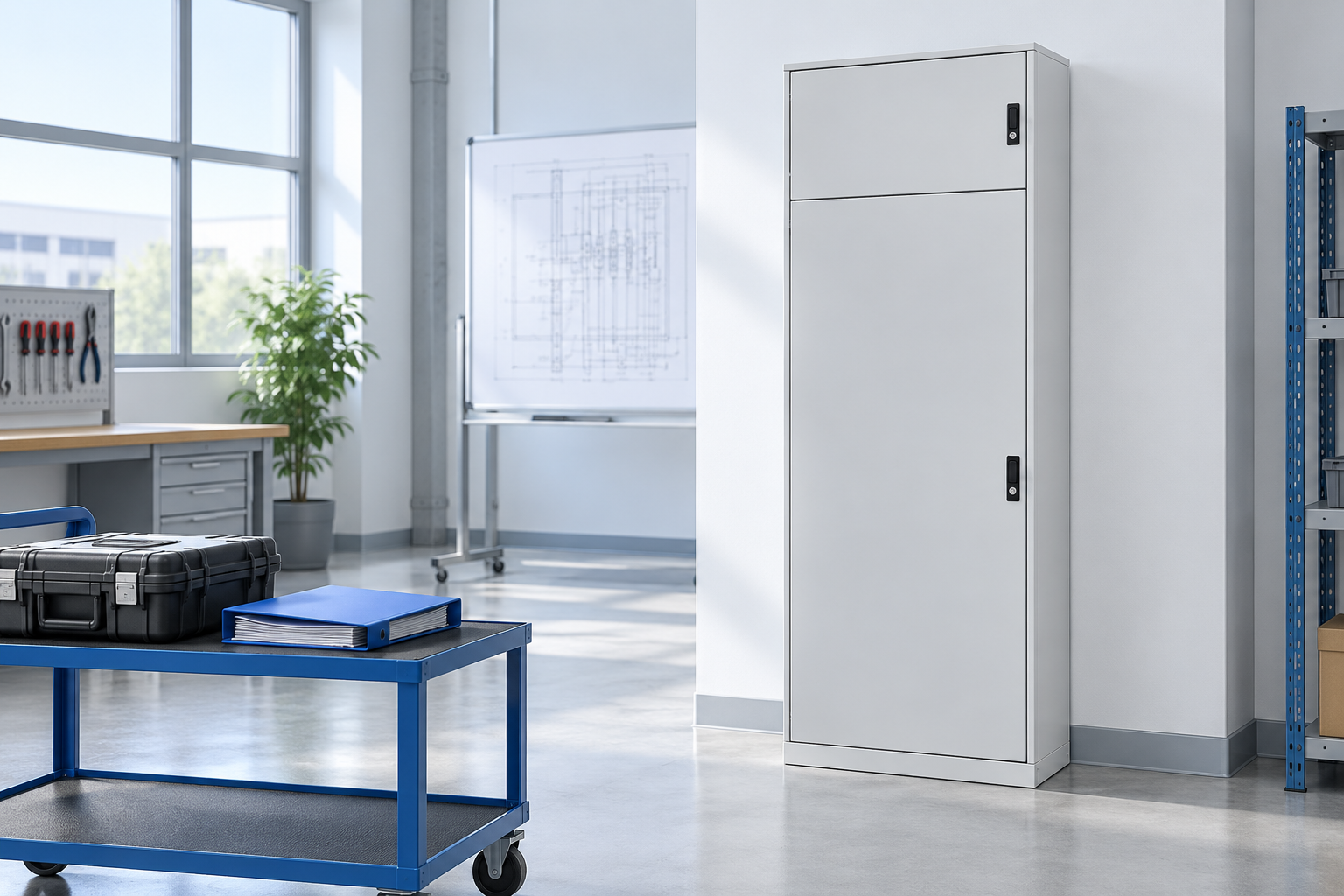
Our low voltage switchgear product page supplies the real cabinet reference used for the illustrations. The pictures are generic equipment and review scenes. They do not depict or establish a certified Form 2, 3 or 4 construction. Obtain the actual proposed arrangement and evidence before making a selection.
Choose an arrangement around documented isolation and access tasks. Reference-based illustration.
Review separation within the complete assembly specification
The form is one part of a larger procurement decision. Rated duties, short circuit conditions, environmental assumptions, temperature rise assessment and the complete verification basis still need review. Use our GGD and MNS switchgear comparison for the wider equipment selection context.
Identify what is fixed at order and how changes will be handled. Additional feeders, substituted devices and revised terminal arrangements should follow controlled design review. Changes that alter separation boundaries require updated drawings and a review of the relevant requirements; an unchanged front label does not establish that the configuration remains acceptable.
Include the agreed layout in the factory acceptance document package. Our switchgear factory acceptance checklist explains the coordination of that review. The separation check should compare the actual ordered construction with accepted drawings rather than requiring a vague demonstration of “quality.”
Acceptance and long term records
At the factory, review identification and configuration with the manufacturer. Confirm that the relevant compartment and termination arrangements agree with the accepted design, and record deviations before delivery. Do not dismantle barriers or undertake improvised tests outside approved procedures to prove a form designation.
At site, check transport condition, installed access and the documentation package before energization. Use the site acceptance guide for the surrounding project coordination. The manufacturer and qualified project team must establish the exact safe checks for the supplied equipment.
Retain the final drawings, isolation instructions, replacement procedure and accepted deviations with maintenance records. Future teams need to know which construction was delivered, where terminals are located and what an alteration may affect. A single form number in an asset list cannot supply that information.
Further learning
The Electrical Engineering Knowledge Sharing video introduces forms of separation in low voltage switchboards. Its educational explanation supports the drawing review vocabulary; it is not operating permission or evidence that the reference cabinet shown in this article has a particular form.
Further learning: Forms of Separation LV Switchboard IEC 61439-2 — Electrical Engineering Knowledge Sharing. Educational background; this is not an operating authorization. Otwórz wideo na YouTube.
Często zadawane pytania
Does Form 4 automatically mean live maintenance is allowed?
No. Safe maintenance depends on approved isolation procedures, equipment instructions, the task and applicable local safety rules. A separation designation does not authorize live work or prove that every accessible part is deenergized.
Is a higher form always the right purchase?
No. Choose the arrangement from actual maintenance, access, outage and expansion requirements. Then verify that the proposed construction and wider assembly specification meet the project’s applicable requirements.
Can a form number prove internal arc performance?
No. Internal arc assessment and its supporting evidence are separate questions. Specify any required performance explicitly and review its applicability to the supplied assembly and installation conditions.
What documents should accompany the form designation?
Request the applicable standard and edition, identified arrangement drawings, terminal layout, isolation boundaries and relevant maintenance instructions. Keep them consistent with the ordered configuration and final accepted records.
Shenheng Electric Power zobowiązuje się do zostania światowym liderem w dziedzinie rozwiązań w zakresie sprzętu energetycznego, pomagając klientom w bezpiecznym, wydajnym i zrównoważonym zarządzaniu energią.

 Shenheng Power Equipment Co., Ltd.