Sinds 2001 is Shenheng Power een vertrouwde fabrikant van apparatuur voor krachtoverbrengst en -distributie en levert wereldwijd betrouwbare elektrische oplossingen.
Ondersteund door een volledig aankoopachterdrachtsysteem, bieden wij deskundig technisch advies, productbegeleiding en flexibele OEM- en ODM-diensten voor uw projecten.
Sinds 2001 is Shenheng Power een vertrouwde fabrikant van apparatuur voor krachtoverbrengst en -distributie en levert wereldwijd betrouwbare elektrische oplossingen.
Ventilatie en warmtebelastingberekening voor schakelruimten
Uitgaafdatum: 2026-10-18
Switchgear room ventilation must remove the room’s actual heat gains while keeping equipment within its approved environmental limits. Start with supplier loss data, the hottest credible incoming air, and a documented operating case. Then calculate airflow, check the complete intake-to-exhaust route, and verify humidity, contamination, fire interfaces and ventilation failure. A fixed air-change rate alone does not establish adequate cooling. This guide explains the room heat balance and the information an electrical buyer should exchange with the mechanical designer; it does not prescribe one universal fan size or authorize changes to energized equipment.
Separate room cooling from cabinet ventilation
The room and the switchgear enclosure are connected thermal systems, but they are not interchangeable. A fan may keep the room average temperature acceptable while warm air collects near upper cabinet compartments. Conversely, adding cabinet ventilation openings may compromise the equipment’s verified enclosure protection or internal-arc arrangement. Obtain the manufacturer’s requirements before altering any cabinet.
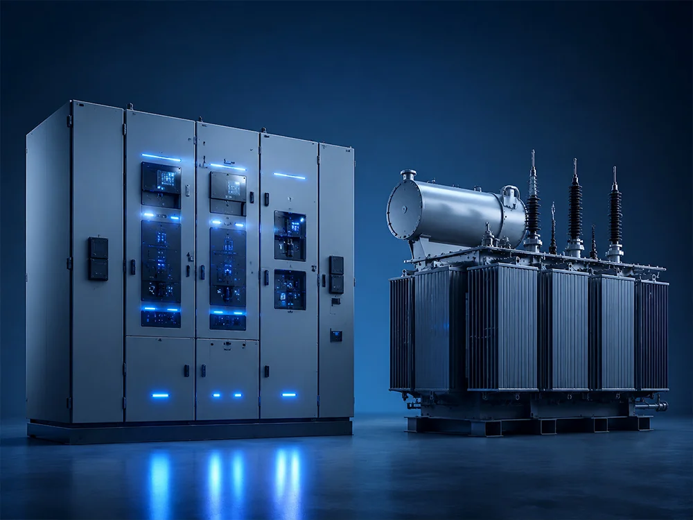
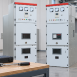
For the equipment context, compare the dimensions and approved operating conditions of the KYN28 middenspanningsschakelinstallatie with the actual room arrangement. The product photograph identifies the equipment family; it does not establish a room cooling duty, a loss figure or a certified ventilation design.
Gebruik de middenspanningsschakelanaloggids to define the lineup and its functions first. This article addresses the heat that must leave the room, rather than repeating equipment selection or transformer-only ventilation guidance.
Build a heat-load register before choosing fans
List each source of sensible heat released inside the room boundary. Include switchgear conduction losses, control power supplies, relays, chargers, lighting and any other permanently operating devices. Identify whether a transformer, UPS or battery system shares the space; these may require separate calculations and additional safety provisions.
Supplier losses should state their operating basis. A figure measured at rated current cannot simply be multiplied by a guessed utilization factor. Some losses vary with current, while auxiliary loads may remain nearly constant. Ask the supplier to separate the components where practical, then let the electrical designer establish credible simultaneous operating cases.
Heat-load input
Bevindingen om te vragen
Besluit dat het steunt
Main-circuit losses
Supplier losses with current and configuration basis
Normal and maximum operating heat
Control and auxiliary loads
Device power and duty schedule
Continuous background demand
Building heat gains
Roof, wall, solar and adjacent-space calculation
Additional room cooling duty
Outdoor design air
Site climate and intake location
Available cooling temperature difference
Verbetering in de toekomst
Defined extra panels and expected duty
Reserved capacity without double counting
Ventilation failure
Operating response and time allowance
Alarm, redundancy or controlled shutdown
This is a project input checklist, not a set of numerical standard limits. Keep the calculation revision tied to the supplier’s approved lineup. A later feeder addition can change both the heat load and the path available for air movement.
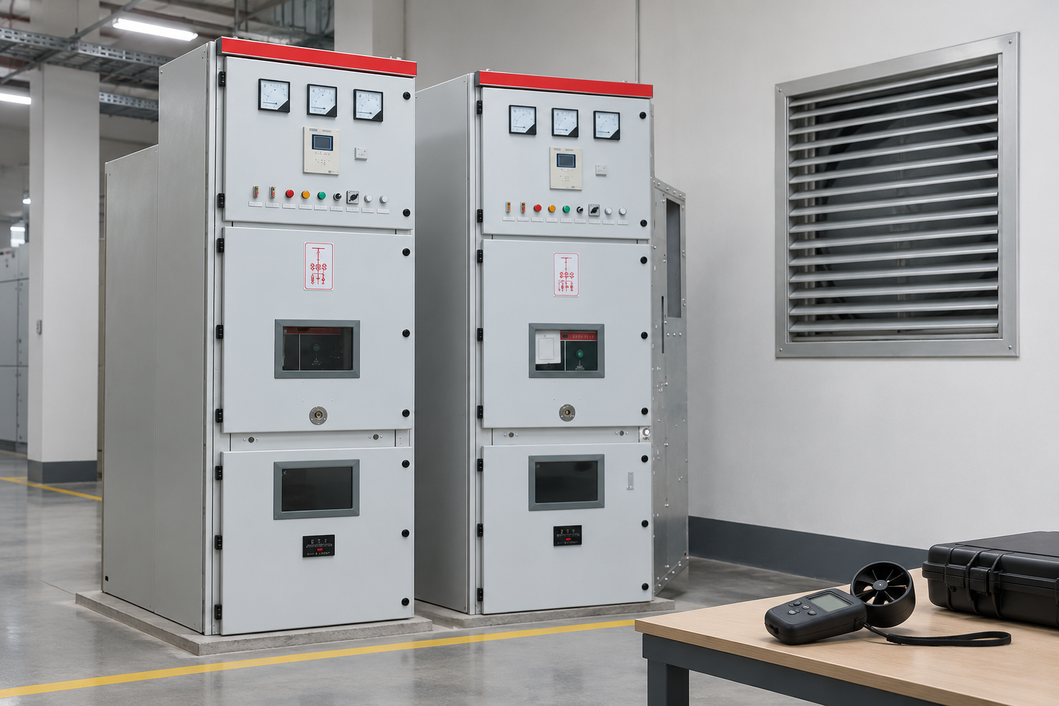
Verify the installed air path and effective airflow. Reference-based illustration.
Calculate airflow from a stated temperature rise
For an initial steady sensible-heat balance, use P = rho × cp × V × delta-T. Here P is the heat carried away in watts, rho is air density in kilograms per cubic metre, cp is specific heat in joules per kilogram-kelvin, V is volumetric airflow in cubic metres per second, and delta-T is the exhaust-minus-inlet air temperature in kelvin.
Rearranging gives V = P / (rho × cp × delta-T). The DOE ventilation research report, Appendix B describes the same sensible-energy relationship using airflow, air properties and temperature difference. Its research application is different; the equation alone does not establish switchgear environmental limits.
For an illustrative calculation, assume a documented room sensible load of 6,000 W, air density of 1.20 kg/m³, specific heat of 1,005 J/(kg·K), and an allowable exhaust-to-inlet rise of 8 K. The resulting airflow is 6,000 / (1.20 × 1,005 × 8) = approximately 0.622 m³/s, or 2,239 m³/h. These are assumed example inputs, not losses or temperature limits claimed for a Shenheng product.
The result is an effective heat-carrying airflow, not a fan catalogue selection. Check the air properties for altitude and temperature, the permissible local temperature around the equipment, and losses through louvers, filters and ducts. Short-circuiting supply air directly to an extract can make the installed airflow much less useful than this ideal balance suggests.
Check whether outside air can do the job
If the proposed inlet air is already warmer than the permitted equipment environment, adding more outside airflow cannot cool the room below that inlet temperature. Refrigerated cooling or another engineered heat-rejection method may be needed. Do not create a negative or near-zero temperature difference in the formula and interpret the output as a workable fan requirement.
Air-change rates remain useful as a descriptive cross-check. For a hypothetical 180 m³ room, the example airflow corresponds to about 12.4 room volumes per hour. That figure follows from the assumed heat balance; it is not a minimum ventilation rate for every switchgear room.
Verify the real air path and pressure losses
Draw the complete route from outdoor intake to equipment zone and discharge. Record louver free area, filters, screens, silencers, dampers, duct bends and the proposed fan operating point. Nameplate fan airflow at negligible resistance is not proof that the installed system delivers the calculated quantity.
Intake and discharge positions should discourage immediate recirculation. Check whether partitions, cable trenches, future panels or stored materials create stagnant pockets. Keep access to withdrawable equipment and escape routes clear; coordinate the design with the switchgear room layout guide.
Natural ventilation needs its own buoyancy and resistance assessment. Large-looking wall grilles do not prove adequate effective opening area. Mechanical ventilation can make airflow more predictable, but introduces power, controls, maintenance and failure dependencies. Compare options using the same heat-load cases rather than different optimistic assumptions for each option.
Keep moisture and contamination in the design
More outside air is not automatically better for insulation reliability. Rain entry, salt, dust and humidity can create problems that cooling calculations overlook. The National Grid switch-room heating, dehumidification and ventilation directive, dated October 2013, warns about excessive ventilation and temperature variation in humid environments. It is a utility-specific historical reference, not a universal current requirement for every project.
Ask the designer how condensation will be prevented during overnight cooling, seasonal change and equipment shutdown. Relative humidity alone is insufficient without temperature and dew-point context. Filter maintenance and drain arrangements also need physical access. Avoid directing cold supply air onto a localized cabinet surface without assessing the resulting temperature distribution.
Coordinate room controls with the existing switchgear condensation-prevention approach. Cabinet heaters address a different boundary from room cooling and should not be treated as a substitute for the room’s environmental design. Any gas-specific ventilation, battery ventilation or smoke-control requirement requires its own applicable assessment.
Plan controls for operating and failure cases
Define where sensors are installed and what each alarm means. A sensor next to the intake can report satisfactory conditions while the equipment zone overheats. Sensor locations should represent the spaces whose temperatures are limited, and should be accessible for calibration without entering restricted equipment compartments.
Agree the response to a stopped fan, blocked filter or failed cooling unit. Options can include a standby unit, an alarm with operator action, load restriction or an engineered shutdown sequence. The choice depends on how quickly temperatures rise, operational consequences and the approved protection philosophy. Do not assign a generic grace period without supporting analysis.
Controls must also respect fire and smoke requirements. A normal cooling fan may be required to stop or change state under an approved emergency sequence. Record this interface explicitly so the electrical and mechanical packages do not issue contradictory commands.
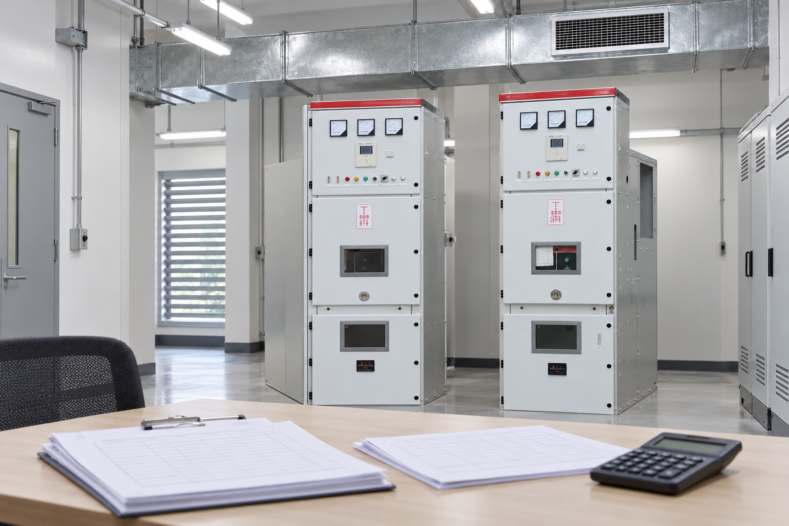
Retain the heat-load register and acceptance basis. Reference-based illustration.
Commission against measurable acceptance evidence
Before energization, compare the installed intake, discharge and duct routes with the approved drawings. Confirm fan rotation, damper positions, filter specification, control wiring identification and alarm delivery. Measurements and adjustments should be performed by qualified personnel under the project’s safe work arrangements.
Measure delivered airflow under representative resistance conditions, then record temperatures at agreed room locations. Retain the equipment load, outside conditions and operating configuration with every reading. A cool morning with unloaded switchgear cannot independently demonstrate performance on the hottest full-load day; use the agreed calculation and commissioning method to close that gap.
Include a safe functional test of alarms and standby operation where specified. Preserve baseline filter pressure drop and access instructions for maintenance. If performance is inadequate, investigate short-circuiting airflow, unexpected heat gains and restrictions before merely increasing fan speed. That change may raise noise and power use without solving the equipment-zone problem.
Video: understand airflow distribution before reviewing the room
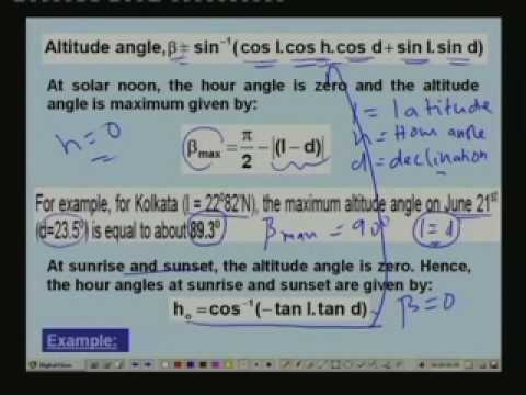
The educational video below supports the airflow and heat-removal principles discussed here. Apply those principles through the project’s mechanical design and equipment limits; the video does not certify an electrical room or replace the calculation and acceptance record.
Further learning: Lecture – 39 Cooling & Heating Load Calculations — nptelhrd. Educational background; this is not an operating authorization. Open de video op YouTube.
Procurement information that prevents late redesign
Send the mechanical designer the approved lineup dimensions, room layout, supplier losses, operating cases and environmental limits together. Ask for a calculation that identifies where every input came from. A single unexplained cooling-capacity number is difficult to review or maintain when the project changes.
Request the fan duty point, filter allowance, sound criteria, power supply, sensor locations, alarm matrix and maintenance route. State which contractor supplies louvers, fire dampers, controls and penetrations. These package boundaries often explain why a complete cooling unit arrives without a complete working installation.
For expansion, distinguish space reserved for equipment from cooling capacity actually installed. Record the trigger for recalculating loads and the physical path for adding capacity. This preserves a usable engineering decision rather than an unsupported promise that the room is future-proof.
Veelgestelde Vragen
Is a fixed number of air changes enough for switchgear room ventilation?
No. Air changes describe airflow relative to room volume. Adequacy depends on actual heat load, incoming air temperature, useful airflow distribution and the equipment’s approved environmental limits. Establish the heat balance first and use air changes as a cross-check.
Can ordinary ventilation replace air conditioning?
Only when the incoming air and effective airflow can maintain the required environment under the design conditions. If outdoor air is too warm, humid or contaminated, a different cooling or conditioning solution may be needed. Document the decision rather than assuming one approach suits every site.
Should the switchgear rated current be used as the heat load?
No. Current is not a heat quantity. Obtain equipment loss data with an operating basis, add other room gains and evaluate the credible load cases. Do not convert the lineup’s electrical throughput directly into room cooling duty.
What should be retained after commissioning?
Keep the approved heat-load register, airflow calculation, equipment limits, fan duty, measured airflow, temperature locations, operating conditions, control tests and maintenance instructions. These records allow later changes to be evaluated against the original design basis.
Shenheng Electric Power streeft ernaar om een wereldwijde leider te worden in oplossingen voor elektrische apparatuur en helpt klanten om een veilig, efficiënt en duurzaam energiebeheer te realiseren.

 Shenheng Power Equipment Co., Ltd.