Sejak 2001, Shenheng Power telah menjadi pengeluar peralatan penghantaran dan pengagihan kuasa yang bertauliah, menyampaikan penyelesaian elektrik yang boleh dipercayai di peringkat global.
Disokong oleh sistem selepas jualan yang lengkap, kami menyediakan perundingan teknikal pakar, panduan produk dan perkhidmatan OEM & ODM yang fleksibel untuk projek anda.
Sejak 2001, Shenheng Power telah menjadi pengeluar peralatan penghantaran dan pengagihan kuasa yang bertauliah, menyampaikan penyelesaian elektrik yang boleh dipercayai di peringkat global.
Restricted Earth Fault Protection for Transformers
Release Time: 2026-10-12
Restricted earth fault protection for a transformer compares current entering and leaving a defined earth-fault zone, normally around a grounded star winding. It can detect winding earth faults that produce too little current for a less sensitive protection element, while remaining stable for faults outside the zone. The word restricted describes the current-transformer boundaries; it does not mean a smaller version of ordinary feeder earth-fault protection. A usable scheme depends on the winding connection, neutral grounding, CT arrangement, relay algorithm and tested trip paths. Start with those inputs before discussing a pickup setting or buying a relay.
Define the protected zone before choosing settings
Draw the three phase CT locations, the neutral CT and every conductor crossing the proposed boundary. Identify the transformer winding included in the scheme and show where the neutral joins the grounding system. A line on a drawing is insufficient if the actual CT is installed on another side of a cable termination. The installed location determines which equipment the relay can observe.
For a grounded star winding, the relay compares the residual of the phase currents with the neutral current using its specified polarity convention. During an external earth fault, the currents should balance after ratio conversion. An internal earth fault changes that balance. Describing the comparison as a simple arithmetic sum without stating current direction and reference can lead to a wrong commissioning test.
Record any neutral branches, grounding resistors, parallel neutral connections and alternative return paths. A neutral CT that measures only one of several return paths can invalidate the intended comparison. Investigate the complete arrangement rather than assuming the neutral connection visible beside the transformer is the only path. The approved protection drawing must match the as-built system.
Transformer differential protection compares currents across the transformer as a whole. REF focuses on earth faults within a particular winding zone. These functions solve different measurement problems, so adding REF is not an admission that the main differential relay is defective. A project may need both functions to achieve the intended coverage.
An earth fault near the neutral end of a star winding may be driven by a relatively small winding voltage. The resulting current also depends on grounding impedance and fault resistance. It is therefore unsafe to promise that every internal fault will produce a large phase differential current. REF can provide useful sensitivity, but its actual coverage must be demonstrated for the transformer and grounding arrangement.
Do not interpret REF as protection for every transformer fault. It does not replace phase-fault protection, overfluxing protection, thermal monitoring or mechanical protection where applicable. It also does not automatically protect cables outside its CT boundary. Use the existing transformer differential protection guide to keep whole-transformer differential decisions separate from this winding earth-fault scheme.
High-impedance and low-impedance schemes
High-impedance REF uses an arrangement intended to remain stable when unequal CT performance creates spill current during an external fault. Its application can involve CT excitation requirements, secondary resistance, a stabilizing resistor and voltage limitation. Those items are a coordinated design. Replacing one CT or shortening one lead does not authorize recalculating the scheme from a generic internet formula.
Low-impedance REF uses the selected relay’s current inputs and operating logic. Depending on the implementation, ratio matching, restraint and external-fault discrimination are handled within the relay. That flexibility does not remove CT requirements. The designer must still assess the signals available during severe through faults and apply the manufacturer’s documented rules.
The practical distinction is the evidence needed to approve the scheme. For high-impedance protection, request the complete CT and secondary-circuit calculation. For low-impedance protection, request the relay-specific application calculation and stability assessment. Neither label alone proves greater sensitivity, better reliability or compatibility with the existing panel.
Review item
High-impedance REF
Low-impedance REF
CT evidence
Excitation characteristics, winding resistance and matching required by the scheme
Ratio, accuracy and transient performance required by the selected relay
Secondary circuit
Lead resistance and stabilizing components are central design inputs
Input allocation, polarity and relay configuration must match the installed circuit
External fault stability
Verify the complete voltage and CT performance calculation
Verify the documented restraint or discrimination behavior and test cases
Replacement approval
Recheck the full circuit when a component changes
Recheck configuration, CT compatibility and application limits
This is a qualitative review table, not a list of standard acceptance limits. The NPTEL power system protection course includes CT saturation and REF as distinct application topics; use that educational background alongside the selected relay documentation.
Grounding and CT decisions that affect sensitivity
The transformer neutral arrangement sets the earth-fault current environment. A solidly grounded system and a resistance-grounded system cannot be treated as interchangeable. Confirm normal and contingency grounding conditions, including whether a neutral connection changes when transformers operate in parallel. Review the neutral grounding methods before fixing the scheme’s assumptions.
Choose the phase and neutral CT ratios together with the relay’s available matching range. A neutral CT ratio selected only for a large maximum current may leave inadequate measurement resolution for the intended sensitive function. Conversely, a low ratio cannot be approved without checking the maximum fault duty and CT performance. The correct choice follows the complete application.
List the actual secondary burden, including leads, terminals and connected devices. Keep protection and metering circuits distinct where the design requires it. Verify polarity using the approved drawing and tests rather than cabinet labels alone. Never open an energized CT secondary; inspection and testing belong to qualified personnel working under the site’s isolation procedures.
CT saturation can create an apparent imbalance during an external fault. The NPTEL explanation of DC-offset CT saturation explains why a secondary waveform may cease to reproduce the primary current faithfully. A sensitive pickup setting must therefore be assessed together with stability, not approved as an isolated number.
Build a commissioning plan around both operation and restraint
Begin with drawing verification and circuit identity. Confirm the CT cores, ratios, terminal numbers, neutral path and relay input assignments. Save the approved settings file, firmware version and logic diagram before testing. A successful injection test against an undocumented temporary configuration is weak evidence of the installed scheme.
Test an internal-fault condition that should operate and an external-fault condition that should remain stable. Verify polarity and ratio compensation using the relay manufacturer’s test method. Include the relevant minimum sensitivity case and the external-fault stability cases defined by the protection study. Secondary injection alone cannot prove the physical primary CT installation.
Then test the complete action chain: relay operation, output contacts, lockout where used, circuit-breaker trip, alarms and event recording. Confirm which breakers isolate all sources feeding the protected zone. A correct relay indication with a missing trip destination leaves the transformer inadequately protected. Document any blocked outputs used during testing and prove their restoration.
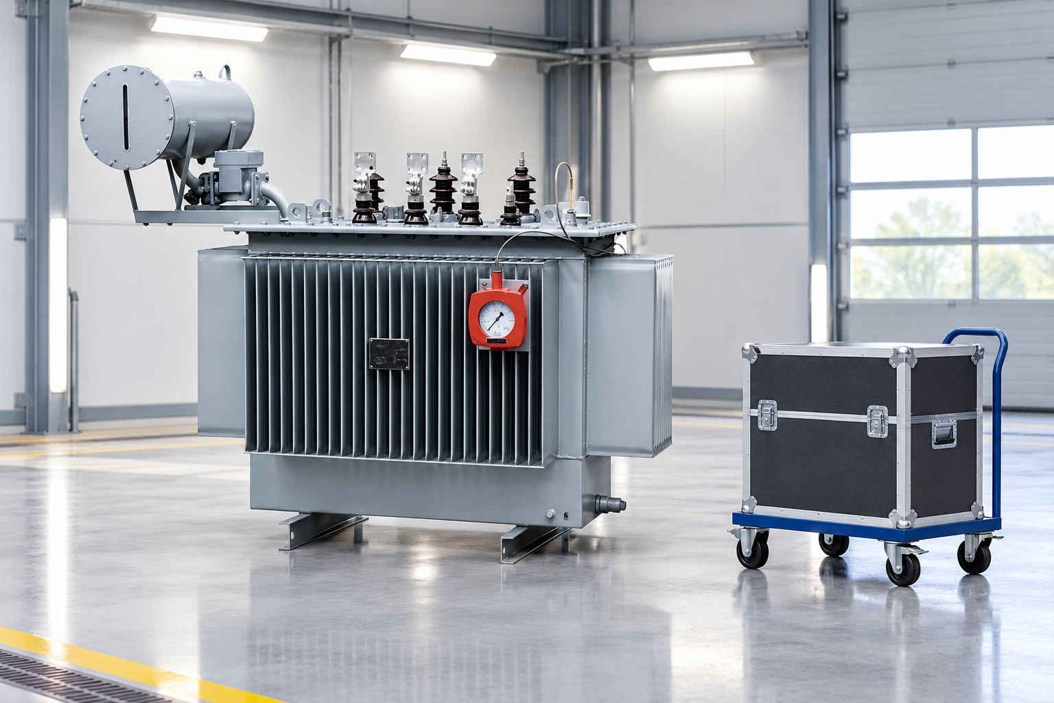
Commissioning must verify operation and external-fault stability. Reference-based illustration.
The Bureau of Reclamation’s FIST manuals provide a public reference for protective-relay field testing and settings management. Their facility context does not replace the site’s own procedures; the useful principle is to preserve controlled test evidence and an approved configuration throughout the work.
Questions to include in the transformer and panel inquiry
For a project using an oil-immersed industrial power transformer, state the winding connection, available neutral terminal, grounding arrangement and required protection functions. Ask who supplies the phase and neutral CTs, who performs the protection calculation and who owns the final settings approval. These responsibilities should be explicit before order placement.
Request the CT data, secondary drawings, relay model and firmware, REF application calculation, trip matrix and planned acceptance tests. Ask whether the quoted panel includes the complete REF circuit or only a relay capable of supporting the function. A capability listed in a catalogue does not establish that the supplied assembly is wired and commissioned for it.
Avoid copying settings from a transformer of similar capacity. Capacity alone does not describe grounding, CT location, fault level or the relay algorithm. Also avoid approving a scheme from a photograph: the illustrative images here show the relevant product family, not internal winding connections or a certified protection arrangement. Verify those details from controlled drawings.
Further learning: CT behavior and winding earth-fault protection
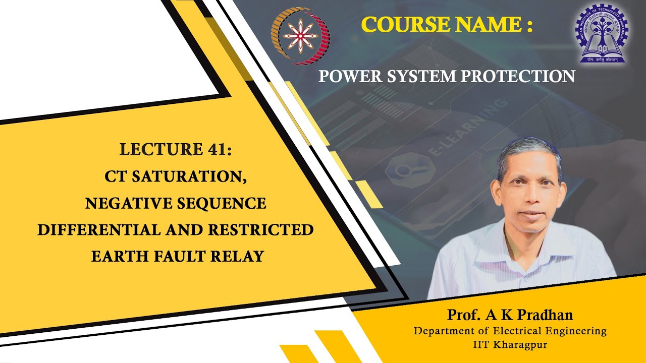
Further learning: Lecture 41 : CT Saturation, Negative Sequence Differential and Restricted Earth Fault Relay — NPTEL IIT Kharagpur. Educational background; this is not an operating authorization. Buka video di YouTube.
Use the lecture to understand why current measurement and external-fault behavior matter. It is educational background, not a field wiring instruction. For the associated measurement decisions, consult the switchgear protection CT selection guide, then apply the specific transformer protection design.
Soalan Lazim
Is REF the same as ordinary earth-fault overcurrent protection?
No. Ordinary earth-fault overcurrent responds to measured earth-fault current according to its settings and coordination. REF compares currents at a defined boundary to distinguish an internal winding-zone earth fault from an external fault. Both functions may be required, but their coverage and operating logic differ.
Can every transformer use restricted earth fault protection?
The application depends on winding connections, neutral availability, grounding and the relay scheme. A grounded star winding is a common application, but the same arrangement cannot be assumed for a delta winding or an inaccessible neutral. The protection designer must confirm the suitable scheme.
Does low-impedance REF remove the need to check CT saturation?
No. The relay may provide restraint and additional discrimination, but the available CT signals still determine what it can measure. Apply the relay-specific CT requirements and assess severe external-fault conditions before approving sensitivity or stability.
What should be retained after commissioning?
Keep the approved drawings, CT data, settings file, firmware record, test results, trip-matrix verification and restoration checklist. Together they establish what was installed and tested, and provide a controlled starting point for future changes or fault investigations.
Shenheng Electric Power komited untuk menjadi peneraju global dalam penyelesaian peralatan kuasa, membantu pelanggan mencapai pengurusan kuasa yang selamat, cekap dan mampan.

 Shenheng Power Equipment Co., Ltd.