
 申恒電力設備有限公司.



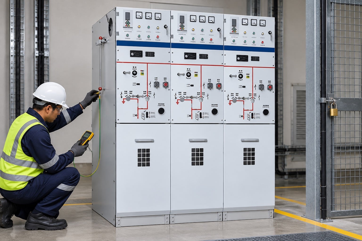
ring main unit earthing needs a clear engineering boundary before it can support a purchase, inspection or commissioning decision. Ring main unit earthing is the controlled connection of the RMU enclosure, earth bar, cable screens, transformer or feeder earths and the site grounding system. It is not simply a green-and-yellow conductor attached to the cabinet. The arrangement must match the one-line diagram, the supplied SF6 RMU construction, the cable accessory design and the approved switching and safety procedure. A visible earth switch handle does not prove that every bonding path is intact.
What must be bonded
Identify the main earth bar, enclosure panels, doors, removable covers, cable screen or sheath connections, transformer tank where applicable, surge arrester earths and the site earth grid connection. The exact list depends on the RMU configuration. The drawing should show the intended paths and any test links or removable bonds.
Keep protective bonding separate from assumptions about neutral grounding. A cable screen may have a specific single-point or both-end bonding arrangement, while the enclosure requires a continuous protective path. Ask the supplier to mark the boundary and connection points on the as-built drawing.
Earth switch and interlocking
The earth switch must operate only in the approved condition and must give a clear mechanical and electrical indication. Interlocks should prevent an impermissible operation, but an interlock is not a substitute for the site isolation, absence-of-voltage verification and grounding procedure. Test the exact RMU mechanism and record the result.
Confirm that the earth switch is rated for the intended duty and that its position indicator agrees with the actual mechanism. Check key interlocks, trapped-key schemes, remote indications and local controls. Never force a handle or bypass a lock to complete a commissioning checklist.
Cable screens and terminations
Cable screen connections should be mechanically secure, correctly identified and routed without sharp bends or unintended contact. Verify stress-control components, gland plates, screen earth leads, test points and the termination manufacturer instructions. A screen connection that looks complete may still be landed on the wrong feeder or left electrically discontinuous.
When a cable withstand or diagnostic test is performed, coordinate the RMU boundary with the cable and accessory supplier. Isolate or protect surge arresters, voltage indicators and sensors as required by the approved method. After testing, discharge and re-ground the cable, restore every bond and cap, and independently check the final configuration.
Continuity and resistance checks
Define the test boundary before measuring continuity or resistance. Record the instrument, lead arrangement, test current, points tested and environmental condition. The acceptance value belongs to the project specification, manufacturer instruction or applicable standard. Do not invent a universal ohmic limit because two RMUs have the same voltage rating.
A four-wire low-resistance test may be useful for a main bond or joint, but it cannot reveal every hidden interface. Visual inspection, torque or connection records and comparison with the drawing remain necessary. If a reading is unstable, investigate contact pressure, paint, corrosion or parallel paths before accepting it.
Earthing during maintenance
The operator needs a clear sequence for isolating the feeder, proving absence of voltage, closing the earth switch and applying any portable grounds required by the site procedure. The sequence must identify all sources, including backfeed, transformer LV paths, generators and adjacent circuits.
Labels, mimic diagrams and remote status should be checked against the physical apparatus. A remote “earthed” indication is helpful but is not proof of a local safe state. Keep permits, locks, tags and independent checks aligned with the switching program.
Fault duty and touch voltage
The site grounding study determines how fault current divides through the earth grid, cable screens, enclosure and other metallic paths. Review touch and step voltage, conductor thermal duty, earth grid connections and the clearing time used in the study. The RMU earth bar should not be selected in isolation from the whole installation.
If the network fault level, clearing time or transformer connection changes, revisit the earthing design. A larger conductor alone may not solve a touch-voltage issue if the grid geometry or bonding path is wrong. Keep the approved study and equipment data together.
機器の境界を定義する
正確な資産、電圧クラス、構造、およびリリースされた図面から始めましょう。有用なエンジニアリングの回答は、物理的な境界と定義された動作状態と結びついています。検査または計算の開始と終了の場所を記録し、意図的に除外された機器を特定します。これにより、一般的なカタログ記述がプロジェクトの承認値と混同されるのを防ぐことができます。.
設計、調達、および導入を通じて製品の同一性を維持してください。付属のモデル、付属品、筐体、ケーブルインターフェース、および環境仮定をメモしてください。設置された配置が図面と異なる場合は、別の製品ファミリーから欠落した値を入力するのではなく、停止して承認された配置を取得してください。.
標準規格とメーカーの証拠を併用する
標準規格はフレームワーク、テストコンセプト、用語を定義しますが、メーカーのドキュメントは供給された機器の検証された構造および動作限界を規定します。標準化されたリンクは、未検証の変更が許容されることを証明するものではなく、パンフレットはプロジェクト仕様または安全規則に代わるものではありません。.
調達については、標準版、設計検証またはタイプテストの範囲、日常検査記録、設置制限、および高度や環境の補正を依頼してください。証拠は資産記録に保管してください。結果が異議を唱えられた場合は、数値の比較前に定義、試験条件、および境界条件を比較してください。.
設置および試運転計画
設置の品質は、現場で音響設計がそのまま残るかどうかを左右します。電源投入前に、基礎、アクセス、持ち上げ、クリアランス、換気、ケーブルの曲げ半径、アース接続、ラベル、および制御インターフェースを確認してください。承認済みの方法書および許可システムを使用してください。きちんとしたキャビネットは、すべての接続、インターロック、またはセンサーが正しく接続されていることを示すものではありません。.
稼働開始は文書確認から視覚検査、機械動作、電気的連続性、機能的論理、保護または制御試験、最終的な修復へと移行すべきです。機器の識別、設定、原値、例外、および検査を行った担当者の記録を記録してください。テストまたは検査により危険性が生じる場合は、機器を隔離してください。.
制御の変更と引き継ぎ
障壁、ケーブルルート、リレー設定、タップ位置、冷却経路、または接地接続の変更は、元の設計の基礎を変化させる可能性があります。制御された変更プロセスを実施し、所有者、技術レビュー、図面の修正、および受諾の証拠を保持してください。一時的なテスト手順は引き渡し前に撤去または明確に記名する必要があります。.
最終的なパッケージには、現況図面、試験シート、承認済みの設定、機器の識別情報、メンテナンス手順、逸脱点、およびトレーニング記録を含めるべきです。将来のオペレータは、メモリーやラベルのない写真に頼ることなく、その決定を再現できるようになるはずです。.
安全上の注意
電気機器はエネルギーを保持し、複数の供給源から電力を供給を受けることができます。この記事はスイッチングに関する指示ではありません。資格を有する職員は、地域の規制、絶縁、電圧の有無の確認、接地、監督の要件に従わなければなりません。電力を供給されているコンパートメントに手を伸ばしたり、ロックを解除したりして測定を行ってはなりません。.
テストが失敗した場合、筐体が損傷している、異常なノイズや放電が発生している、実際の構成が不明な場合は、資産を安全な状態に維持し、担当エンジニアに報告してください。診断なしでの繰り返し電源投入は損傷やリスクを増大させる可能性があります。.

プロジェクトでその結果をどのように利用するか
まず、リリースされた設計と最終的な機器の仕様から始めましょう。操作状態、測定ポイント、環境条件、およびその決定の根拠を記載してください。その後、記録を該当する標準、製造元の指示、およびプロジェクトの承認計画と比較します。前提条件が欠けている場合は、一般的な値でそのギャップを埋めるのではなく、その項目をそのまま残しておいてください。これにより、調達、導入、運用チームに同じ基準が与えられます。.
仕入先からの問い合わせでは、計算方法、確認された手順、制限事項、試験記録、および逸脱点について確認してください。現場作業では、担当者、機器、日付、隔離境界、および復旧確認を記録してください。次のステップの承認に必要な事実を隠してしまう長い報告書よりも、簡潔な記録の方が有用です。.
| 確認 | 証拠 | 決定の使用 |
|---|---|---|
| 定義 | 境界、機器の識別、および動作状態 | 異なるチームが異なる数量を比較することを防ぎます。. |
| 設計基準 | 評価、環境、および義務の前提条件 | 解答と実際のインストールをリンクします。. |
| 確認 | 承認された方法、器具、生の結果、および承認基準 | 監査可能な記録を作成します。. |
| 変更管理 | 偏差値、レビューオーナー、および構築時点での修正内容の確認 | 隠れたフィールドの変更がリスクとなるのを防ぐ。. |
| 引き継ぎ | 設定、テスト、写真、メンテナンス、および例外 | 安全な将来の運用をサポートします。. |
関連製品およびエンジニアリングガイド
Shenheng製品の組み合わせに関する詳細は、こちらをご覧ください。 該当する製品ページ. より広範なトピックについては、こちらをお読みください。 親エンジニアリングガイド. 関連する記事: 最初の関連ガイド そして 2つ目の関連ガイド.
情報源と基準
システムコンテキスト用の動画
このニュートラルなPractical Engineeringの解説書は、変電所、トランス、配電盤のシステムに関する説明を提供します。これはスイッチングや試験に関する指示ではなく、教育的な背景を提供するものです。.
よくある質問
最初のステップは何ですか?
Identify the exact equipment and define the ring main unit earthing boundary before comparing a number or condition.
カタログページがプロジェクトエンジニアリングを置き換えることは可能か?
いいえ。リンクされた製品ページには、関連するShenheng機器ファミリーが記載されています。付属のモデル、アクセサリー、規格、およびプロジェクトの承認計画が最終的な決定を下します。.
どのような証拠を保持すべきですか?
承認された図面、原資料、写真、試験方法、機器の詳細、偏差、設定、最終的な竣工記録を保管してください。.
この記事はライブワークを許可していますか?
いいえ。資格を有する職員は、現場の電気安全プログラム、絶縁手順、および製造元の指示に従う必要があります。.




