Dal 2001, Shenheng Power è un produttore affidabile di apparecchiature per la trasmissione e la distribuzione di energia, che fornisce soluzioni elettriche affidabili a livello globale.
Supportati da un completo sistema post-vendita, offriamo consulenza tecnica esperta, guida sui prodotti e servizi flessibili OEM e ODM per i vostri progetti.
Dal 2001, Shenheng Power è un produttore affidabile di apparecchiature per la trasmissione e la distribuzione di energia, che fornisce soluzioni elettriche affidabili a livello globale.
How Harmonics Affect Transformer Capacity and Heating
Release Time: 2026-10-03
Transformer harmonic derating means assessing or reducing the permissible loading of a transformer when nonsinusoidal current creates additional losses and heating beyond the conditions assumed by its normal rating. The correct assessment uses the harmonic spectrum, transformer loss information, cooling conditions and applicable engineering method. A single total harmonic distortion value cannot determine a universal derating percentage. Nonlinear loads such as drives, rectifiers and electronic power supplies should be described in the inquiry so the manufacturer can verify the offered transformer’s suitability and any required loading limit.
Why RMS current alone can miss the problem
RMS current is important for conductor and winding heating, but harmonic frequency also affects some loss components. Two current waveforms can have the same RMS magnitude and different harmonic distributions. A thermal assessment that treats both as identical can miss a relevant difference in additional losses.
Begin with the load composition. Identify large converters, their operating modes, filters and the expected simultaneous use. Include future nonlinear loads if they form part of the project. A transformer selected for today’s mostly sinusoidal load may face a different duty after a production expansion.
The RMS example below illustrates waveform calculations. Use it to understand the distinction between current summaries and a capability assessment, then obtain the actual transformer’s thermal and harmonic-duty evidence rather than treating an illustrative number as a product rating.
NPTEL’s DC power transmission course includes converter current harmonics and their system effects. It is useful background for identifying nonlinear-load behavior, while the transformer capability calculation still requires the actual spectrum and design data.
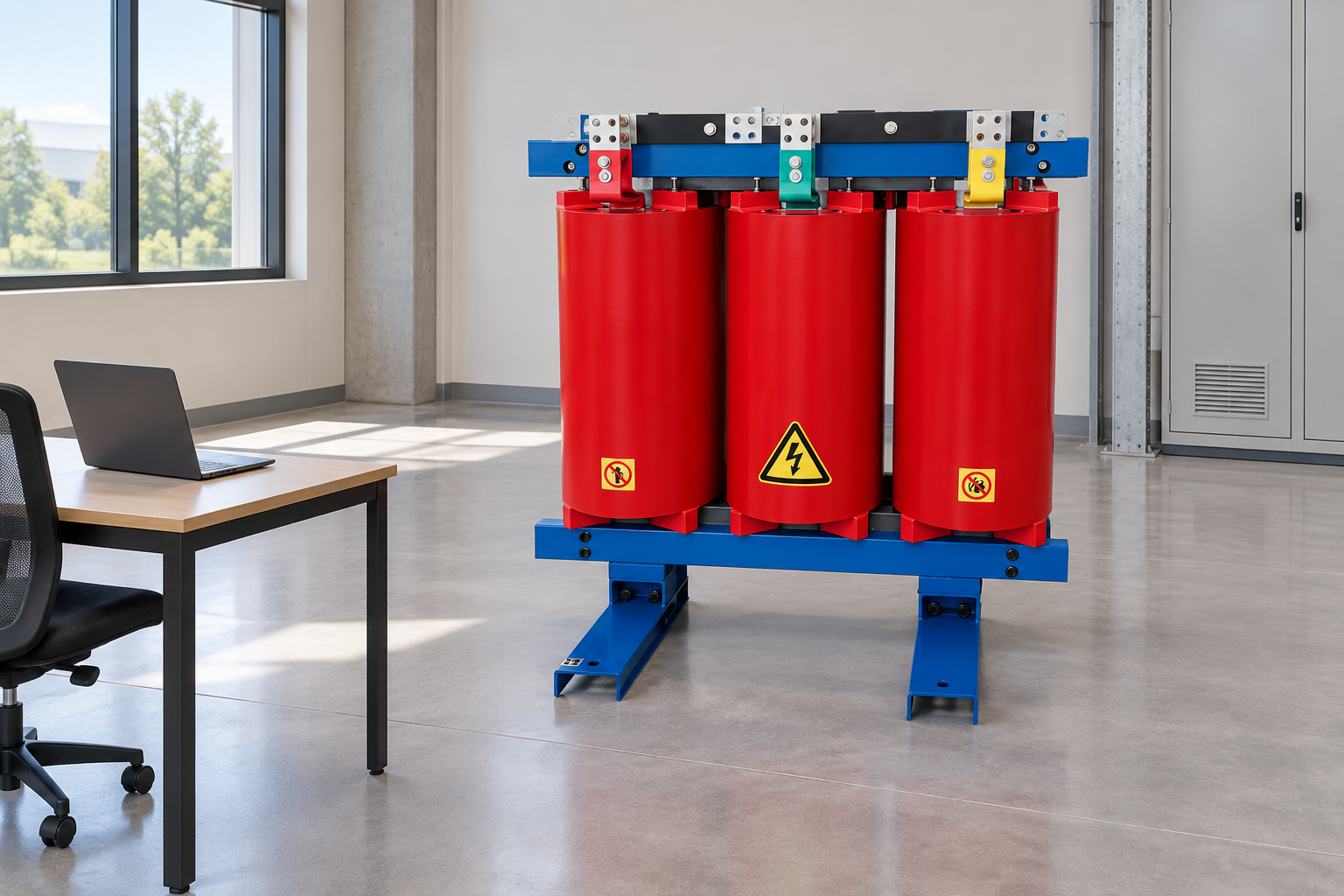
Collect representative waveform and loading data for the capability assessment. Reference-based illustration.
Inputs needed for a useful assessment
Ingresso
Perché è importante
Useful form
Common omission
Harmonic current spectrum
Frequency distribution affects additional losses
Individual harmonic magnitudes with measurement basis
Supplying THD only
Load cycle
Heating depends on duration and simultaneous duty
Time-based loading profile
Using a brief peak as continuous duty
Transformer loss information
The design determines loss response
Manufacturer data for the relevant assessment
Applying another unit’s factors
Ambient and cooling
Thermal margin depends on installation
Room or site data and cooling arrangement
Ignoring enclosure ventilation
Neutral current
Certain harmonic components may affect the neutral
Phase and neutral recordings
Measuring only one phase
Future load changes
New converters can change the duty
Expansion schedule and operating cases
Assessing initial loads only
The table contains qualitative input requirements. IEEE’s transformer capability guidance for nonsinusoidal loads is a relevant standards reference; confirm the edition required by the project and apply the complete method through qualified engineering personnel.
THD is a summary, not a complete design input
Current THD describes harmonic content relative to a reference current component under a defined calculation. It does not tell the reader which harmonic orders dominate or how the spectrum changes through the operating cycle. Measurements also need a clear basis and suitable instrument settings.
Ask for individual harmonic magnitudes, measurement location, load state and recording period. Record whether the measurement represents one device or the combined transformer load. A drive’s brochure data may not reproduce the spectrum at the transformer terminals when many different loads operate together.
Do not assume that currents from separate loads can be added as simple percentages. Their phases and operating conditions can affect the combined waveform. Where measurements are unavailable, the designer should identify the assumptions and uncertainty of the prediction, then establish commissioning measurements to confirm the actual duty.
RMS and a frequency-weighted illustration
For harmonic components expressed in amperes, total RMS current can be calculated as the square root of the sum of squared component RMS values. This equation is a waveform calculation; it does not independently produce a permissible transformer rating.
For a simplified example, consider a 100 A fundamental, 20 A fifth harmonic and 10 A seventh harmonic, with other components omitted. Total RMS current is sqrt(100² + 20² + 10²), or approximately 102.5 A. Fundamental-based current THD is sqrt(20² + 10²) / 100, or approximately 22.4 percent. These are illustrative inputs, not measurements from a website product.
A normalized frequency-squared illustration gives [1² × 100² + 5² × 20² + 7² × 10²] / 102.5², approximately 2.37. This illustrates why higher frequencies can deserve different weighting; it is not a complete loss model, a declared product K-factor or a stand-alone derating rule. Actual capability requires the relevant standard method and transformer loss data.
Separate losses and thermal limits
The assessment should distinguish the loss components used by the selected engineering method and account for the offered construction. It should also identify which thermal limit governs permissible loading. A general statement that harmonic losses are higher does not quantify the allowable load for a particular unit.
Cooling arrangement, ambient conditions and enclosure behavior remain relevant. Harmonic-duty suitability cannot be evaluated independently of room ventilation or the actual operating temperature. If the design relies on fans or another accessory, specify its availability, monitoring and failure response.
K-factor rating and harmonic derating answer different questions
A K-factor-rated transformer is designed or specified for a particular harmonic-duty basis under the applicable framework. Derating evaluates how a transformer can be loaded under the proposed nonsinusoidal current. These concepts are related but should not be treated as interchangeable labels.
Ask the supplier to identify the standard, rating basis, loss assumptions and permitted operating conditions behind any K-factor claim. Confirm that the offered unit is supported by the relevant design and test documentation. A calculated number from a measured waveform is not evidence that an ordinary unit has been manufactured as a K-rated transformer.
Also review neutral conductor and terminal duty, connection, voltage distortion and protection. A suitable transformer does not automatically solve every power-quality issue created by the loads. The project may require a coordinated review of filters, converter selection and the rest of the distribution system.
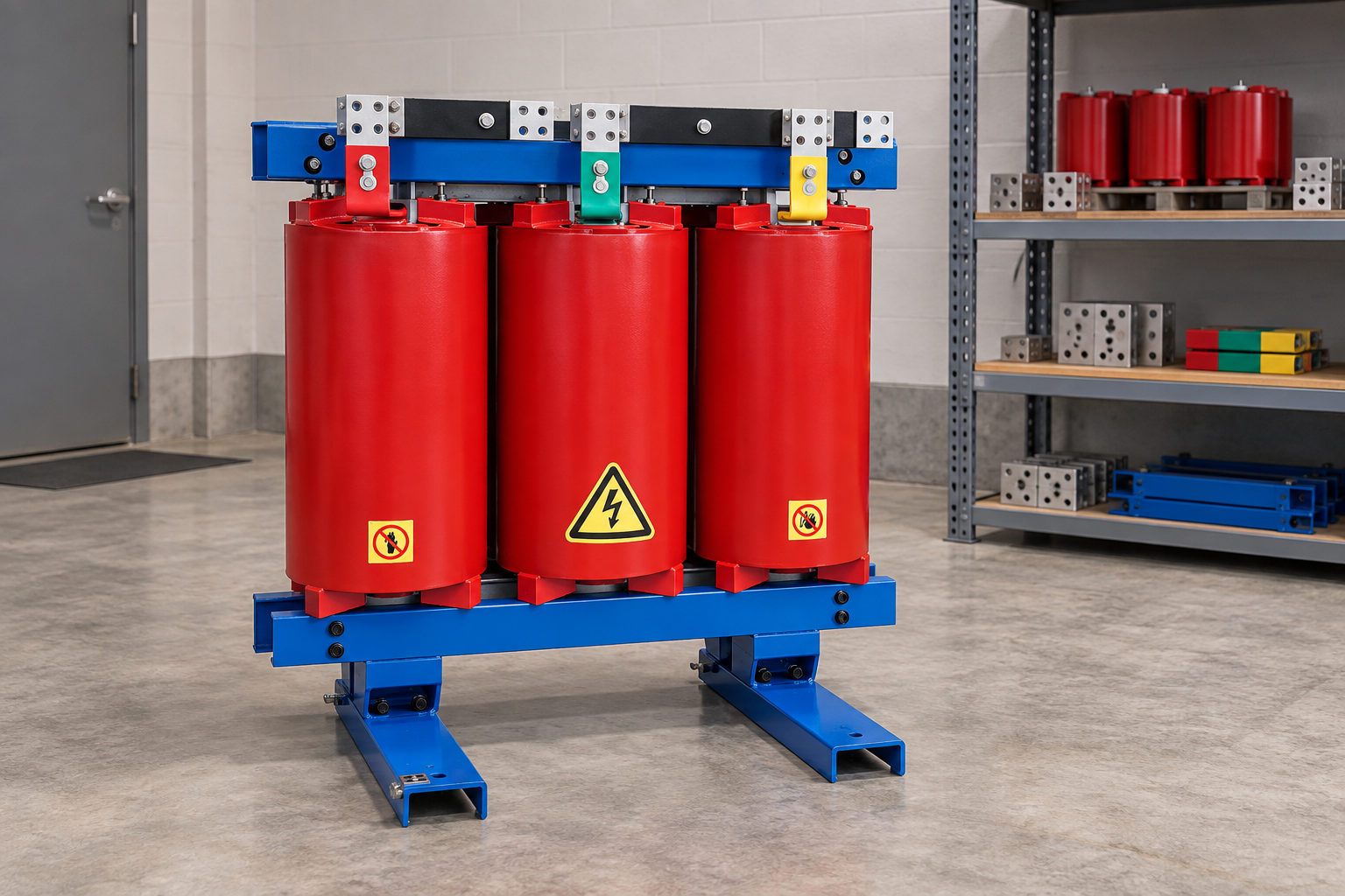
Review cooling and operating limits after nonlinear loads change. Reference-based illustration.
How to obtain representative measurements
Choose a recording period that includes the important operating cases: normal production, high converter loading, low load, startup and any alternative supply condition. Identify the location and instrument capability. Qualified personnel must plan measurements around the site’s electrical safety rules.
Record phase currents, neutral current where relevant, voltages, harmonic spectra and load status. Time-align the records so a change can be associated with an operating event. A spectrum captured without knowing which equipment was running is difficult to use for selecting a future transformer.
If the plant is not built yet, collect equivalent load data from reliable equipment information and state the prediction method. The procurement document should identify uncertainty and require confirmation after commissioning. Avoid presenting a forecast spectrum as a measured fact.
Mitigation should address the cause
Possible responses include an appropriately designed transformer, an approved loading limit, changes to the load arrangement or a power-quality solution. Select the response from the measured or predicted duty and the project requirements. Simply buying a larger unit can be an incomplete solution if the harmonic and neutral-current conditions are not understood.
Filters and converter changes require network review. They can affect resonance, voltage distortion and operating behavior. Ask the responsible engineer to assess the complete system and identify performance under different load states. A proposed filter should not be accepted solely because it reduces one brochure THD figure.
Where an existing transformer is retained, define the permissible operating envelope and the monitoring that supports it. Identify what happens when new loads are connected or cooling becomes unavailable. Operators need an actionable limit and escalation process, not an unexplained percentage in an old calculation.
Match the inquiry to a real product category
The trasformatore a secco incapsulato in resina is a relevant equipment category for an industrial load inquiry. Its listed construction does not establish a harmonic-duty rating. Request written confirmation for the proposed load spectrum, capacity and installation conditions.
Provide winding voltages, frequency, connection requirements, impedance constraints, ambient range, enclosure arrangement and the load spectrum. Ask for the capability assessment, any loading limitation, temperature-rise evidence, neutral-duty details and protection interfaces. Require unsupported assumptions to be identified before purchase.
Usa il industrial transformer sizing guide to describe the base capacity requirement. Then add the harmonic assessment as a separate duty check. This prevents a demand calculation from silently substituting for a thermal capability review.
Acceptance and continuing operation
At commissioning, compare the measured duty with the approved assumptions and verify temperature monitoring. Retain the baseline spectrum, loading profile and instrument information. If the assessment depends on a particular load combination, record how the operator will maintain that condition.
Review the assessment after a major load addition, converter replacement or cooling change. Rising temperature should prompt investigation of loading, cooling and waveform conditions rather than an automatic assumption of one cause. The final action must be based on the complete condition evidence and manufacturer guidance.
Further learning
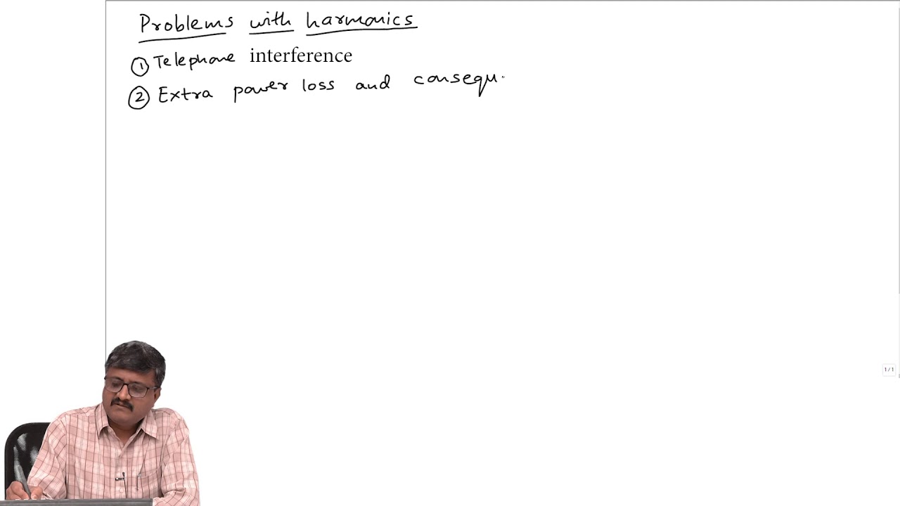
Further learning: Lecture 61 – Problems with harmonics — NPTEL-NOC IITM. This educational video supports the topic; it is not a product demonstration or an operating authorization. Apri il video su YouTube.
Domande frequenti
Can THD alone determine transformer derating?
No. Individual harmonic orders, loss information, load duration and cooling conditions are needed. Two loads with similar THD can present different thermal duty.
Does a larger transformer always solve harmonic heating?
No. Size can affect loading margin, but design, neutral duty, waveform and network behavior still require assessment. Use an approved capability calculation rather than a capacity-only assumption.
Is the example’s 2.37 a recommended K-factor rating?
No. It is a simplified frequency-weighted illustration using three current components. It does not specify a complete transformer design or its permissible loading.
When should the assessment be repeated?
Review it after significant nonlinear-load additions, operating changes or cooling modifications, and whenever measured duty differs materially from the original assumptions.
Shenheng Electric Power si impegna a diventare un leader globale nelle soluzioni di apparecchiature elettriche, aiutando i clienti a ottenere una gestione dell'energia sicura, efficiente e sostenibile.

 Shenheng Power Equipment Co., Ltd.