Dal 2001, Shenheng Power è un produttore affidabile di apparecchiature per la trasmissione e la distribuzione di energia, che fornisce soluzioni elettriche affidabili a livello globale.
Supportati da un completo sistema post-vendita, offriamo consulenza tecnica esperta, guida sui prodotti e servizi flessibili OEM e ODM per i vostri progetti.
Dal 2001, Shenheng Power è un produttore affidabile di apparecchiature per la trasmissione e la distribuzione di energia, che fornisce soluzioni elettriche affidabili a livello globale.
Sistema di messa a terra della sottostazione: progettazione della griglia, tensione di contatto e collaudo
Release Time: 2026-08-31
A substation grounding system is the interconnected grid of buried conductors, ground rods or electrodes, equipment bonds, structures, fences, neutrals, cable shields, and surface treatment that provides a controlled path for fault and lightning current while limiting hazardous touch and step voltages. Good grounding is not achieved by chasing one low resistance number. The design must consider maximum grid current, fault duration, soil resistivity and layering, conductor thermal duty, grid geometry, transferred potentials, human exposure, corrosion, and protection clearing. A qualified grounding study and the project’s governing standard are required before construction.
What the grounding grid must accomplish
During a ground fault, current enters the grounding system and raises the substation grid above remote earth. This grid-potential rise is unavoidable; the safety task is to keep voltage differences that a person can bridge within the design criteria and to ensure conductors survive the event. Bonding exposed conductive parts keeps them near a common potential, while buried geometry and surface material shape the voltage gradient.
IEEE Std 80 provides guidance for safety in AC substation grounding. The current edition and local requirements must be confirmed for each project. IEC-based projects may use other methods. A copied grid spacing or a rule such as “one rod at each corner” is not a design.
Transformers, switchgear, structures, cable systems, fences, and control buildings must be considered as one grounding design.
Main parts of a substation grounding system
Element
Primary purpose
Design concern
Buried grid conductors
Distribute current and control surface gradients
Geometry, depth, thermal duty, corrosion
Ground rods/electrodes
Reach deeper soil and supplement current dispersal
Material resistivity, thickness, moisture, maintenance
Connections
Maintain grid continuity
Fault duty, corrosion, workmanship, inspection
Inputs required for a grounding study
Soil resistivity model
Measure soil resistivity across suitable probe spacings and site locations. One reading cannot describe layered, rocky, filled, wet, or seasonally changing ground. The study converts field data into a soil model and records uncertainty. Measurements taken after importing conductive fill or during an unusual moisture condition may not represent the final site.
Fault current and clearing time
The grid-current calculation is not simply the switchgear short-circuit rating. It considers the portion of ground-fault current entering the grid, return paths through overhead shield wires, neutrals, cable sheaths, adjacent grounding systems, and the fault location. Protection clearing time affects both conductor heating and allowable exposure. Use the approved short-circuit and protection studies.
Site geometry and exposure
Provide the fence, gates, roads, control building, equipment foundations, cable trenches, rails, pipelines, telecom routes, incoming lines, nearby buildings, and public-access areas. Touch and step exposure at the perimeter can govern the design even if values near major equipment are acceptable.
Touch, step, mesh, and transferred voltage
Touch voltage is the potential difference a person can bridge between a grounded object and the surface underfoot. Step voltage is the surface difference between two feet. Mesh voltage is a calculated touch exposure within a grid mesh. Transferred potential occurs when a conductor, shield, pipe, rail, or neutral carries the substation potential to another location—or imports a remote potential into the yard.
Transferred potentials require interface review, not only local grid calculation. Metallic water pipes, telecom cable shields, LV neutrals, fence extensions, and remote panels can create unexpected paths. Isolation, bonding, surge protection, or gradient-control measures must be engineered for the actual system.
Design process
Define the site, governing standards, safety criteria, fault scenarios, and accessible areas.
Measure soil resistivity and develop the justified soil model.
Determine grid current and clearing time from system studies.
Select conductor material and size for thermal, mechanical, corrosion, and life requirements.
Create an initial grid geometry around equipment, structures, fence, and operating locations.
Model grid-potential rise and touch, step, and mesh voltages.
Revise conductor spacing, rods, perimeter control, surface material, and bonds where criteria are not met.
Issue coordinated construction drawings, connection details, material specifications, and inspection points.
Verify the installed system before burial and perform the specified commissioning tests.
Equipment bonding details
Transformer tanks, radiators where required, marshalling kiosks, switchgear frames, operating handles, cable boxes, surge arresters, steel structures, control-building steel, metallic cable trays, fences, gates, and auxiliary systems need defined bonds. A single daisy chain can make downstream equipment dependent on one joint; critical items may require two independent connections to different grid points.
Neutral grounding connections carry system current under specific faults and must not be treated as ordinary equipment bonds. Their route, CT position, parallel paths, and connection to the grid affect protection. Coordinate transformer neutral, grounding resistor or reactor, station service, and LV neutral arrangements with the protection study.
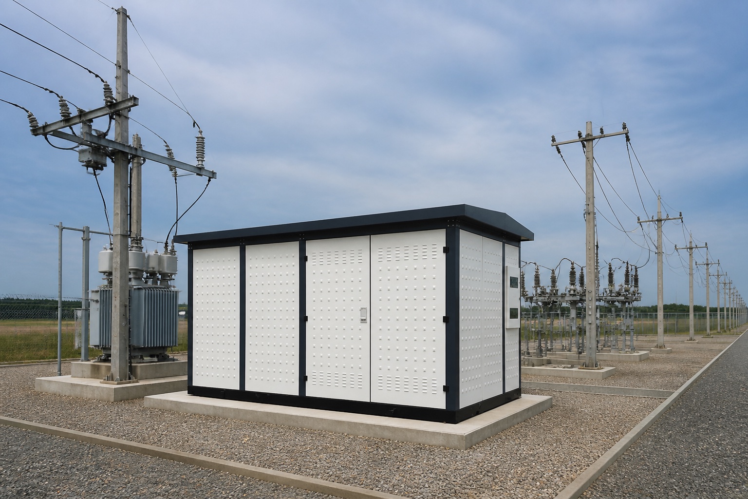
Compact substations still require coordinated bonds for the enclosure, transformer, switchgear, cable shields, neutral, and external site earth.
Construction quality before backfilling
The buried grid becomes difficult to inspect once civil works advance. Establish hold points for conductor depth and routing, connection method, rod installation, foundation interfaces, riser locations, material compatibility, and photographic records. Protect conductors from concrete-work and excavation damage. Keep connections clean and make them with the qualified process.
Update as-built coordinates when the route changes around foundations or services. A drawing that shows the design but not field deviations weakens future testing and excavation safety. Record every accessible test point and equipment bond label.
Commissioning and condition assessment
Commissioning may include visual inspection, continuity testing of the grid and equipment bonds, verification of conductor routing before burial, soil or system measurements, and specialized integrity testing. A simple clamp measurement at one bond does not prove the safety of the entire grid. Test methods, limits, current injection, remote probes, and interpretation depend on the system and standard.
EPRI has researched substation ground-grid condition assessment, reflecting the difficulty of evaluating buried systems. During service, inspect corrosion, broken flexible gate bonds, construction damage, added equipment without bonds, loose accessible joints, fence changes, and civil modifications. Revisit the study when fault levels, clearing times, footprint, soil, or connected metallic systems materially change.
Interpreting measurements responsibly
Test results depend on current paths, probe placement, connected neutrals and shields, soil condition, interference, and instrument method. Compare readings with the study model and earlier tests made under similar conditions. An unexpected value should trigger a setup and grid-configuration review before excavation. Conversely, one satisfactory overall resistance measurement cannot close a defect involving a broken equipment bond or unsafe perimeter gradient.
Grounding and worker safety
A permanent ground grid does not eliminate the need for isolation, absence-of-voltage verification, and temporary protective grounding during work. It also does not guarantee zero voltage during faults. OSHA’s electrical safety resources provide regulatory context in the United States. Switching, equipotential work zones, induced voltage, and temporary grounds require site-specific procedures.
Common grounding mistakes
Using ground resistance as the only acceptance measure.
Assuming uniform soil without adequate field measurements.
Using equipment fault rating as grid current without current-split analysis.
Ignoring the fence, gate, remote panels, pipes, cable shields, and LV neutrals.
Changing conductor routes during civil work without engineering review.
Burying connections before inspection and photographic evidence.
Adding equipment later without updating bonds and the grounding study.
Assuming a surface stone layer permanently retains its original electrical properties.
Grounding information for packaged substations
For a prefabricated or compact substation, the vendor should identify enclosure bonding points, transformer tank bonds, MV/LV switchgear bonds, neutral connection, cable-shield connections, internal conductor size, and interface to the external grid. The project engineer remains responsible for integrating the package into the site grounding study.
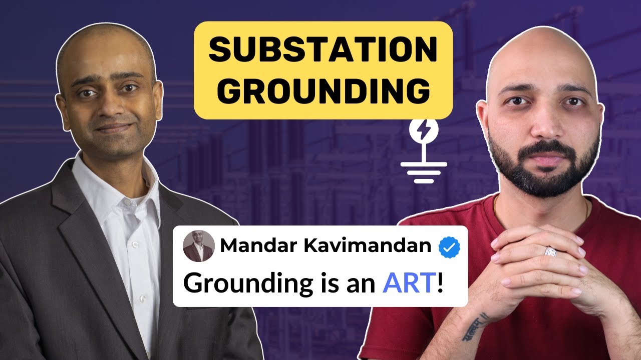
This independent educational video illustrates grounding, step potential, and touch potential. It is conceptual and does not replace a grounding study.
Confine di accettazione: The finished grounding system should be accepted against the engineered study, approved drawings, material and connection requirements, construction inspections, as-built record, and specified tests. A generic target copied from another substation cannot account for this site’s soil, fault-current split, clearing time, accessible areas, or transferred potentials. Unresolved departures require engineering disposition before energization.
Substation grounding system FAQ
What is a good substation ground resistance?
No single resistance value proves safety. The design must meet touch, step, thermal, and project requirements for the actual fault and soil conditions.
Why is crushed rock used in substations?
A suitable high-resistivity surface layer can increase foot-contact resistance and reduce body current, but material properties, thickness, moisture, contamination, and maintenance matter.
Does every item need two ground connections?
Requirements depend on the item, standard, owner practice, and reliability objective. Major equipment often uses multiple deliberate paths; drawings must define them.
When should the grounding study be updated?
Update it when fault current, clearing time, site geometry, equipment, fence, soil conditions, or connected metallic systems change materially.
Can continuity testing prove the grid is safe?
No. It verifies selected conductive paths but does not alone prove soil performance, current distribution, or acceptable touch and step voltages.
Shenheng Electric Power si impegna a diventare un leader globale nelle soluzioni di apparecchiature elettriche, aiutando i clienti a ottenere una gestione dell'energia sicura, efficiente e sostenibile.

 Shenheng Power Equipment Co., Ltd.