Desde 2001, Shenheng Power ha sido un fabricante de confianza de equipos de transmisión y distribución de energía, ofreciendo soluciones eléctricas confiables a nivel mundial.
Respaldados por un sistema postventa completo, ofrecemos consulta técnica experta, orientación sobre productos y servicios flexibles de OEM y ODM para sus proyectos.
Desde 2001, Shenheng Power ha sido un fabricante de confianza de equipos de transmisión y distribución de energía, ofreciendo soluciones eléctricas confiables a nivel mundial.
A switchgear site acceptance test (SAT) verifies that delivered and installed equipment is ready for the next authorized commissioning stage. It checks transport condition, installation, site earthing, cable interfaces, applicable electrical measurements and the complete protection-and-control chain. A useful SAT checklist records the exact circuit, acceptance basis and final installed configuration. It does not treat a factory pass or a collection of disconnected test reports as proof that the whole site scheme will operate correctly.
This guide focuses on medium-voltage switchgear after installation. The actual scope must follow the contract, applicable standards, equipment instructions and site safety plan. Energization is a separate controlled decision made by the responsible authority after the required evidence is accepted.
Define the acceptance boundary and sequence
Identify what SAT covers: delivered panels, transport joints, bus sections, breakers, instrument transformers, cables, earthing, DC supplies, protection and external interfaces. State which items belong to another contractor and how their evidence will be accepted. An interface gap can remain even when each contractor has passed its own component checks.
Agree the sequence so later work does not invalidate earlier tests. Cable termination, wiring changes, relay configuration updates and mechanical adjustments can affect accepted results. The final review should identify changes since testing and the relevant repeat checks.
El NETA acceptance testing standards page describes a field acceptance framework where adopted. Select the applicable edition and contractual requirements. The IEC 62271-200 scope provides product-standard context for AC metal-enclosed switchgear; neither public catalogue page is a substitute for the detailed approved test procedure.
Compare delivered equipment with factory records
Check panel and serial identities against the purchase documents, factory reports and shipping list. Inspect transport condition through the authorized receiving process. Record damage, moisture evidence, missing accessories and changes to the transport arrangement before installation conceals them.
Reconcile the supplied configuration with the approved single-line diagram and panel schedule. Confirm any factory deviations and concessions have been carried into the site plan. A factory release can leave specific site obligations; the installation team must know what they are.
Utiliza el ring main unit commissioning checklist as a related equipment reference, while retaining the actual switchgear-specific procedures. Similar voltage levels do not make RMU and metal-clad panel arrangements interchangeable.
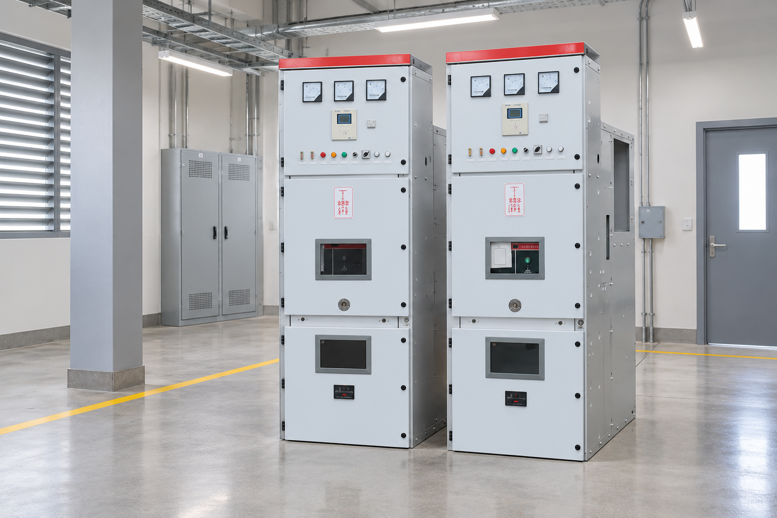
Keep the final configuration and measurement boundaries traceable. Reference-based illustration.
Inspect the final installed arrangement
Verify the equipment position, panel sequence, alignment, support and agreed access against the final layout. Check that transport sections and site joints have been assembled through the approved instructions. Retain the relevant installation records, including specified connection checks, rather than relying on a visual impression.
Confirm that the room, ventilation, environmental conditions and cable interfaces meet the project’s requirements. Review door and operating access, maintenance space and any pressure-relief or exhaust arrangement specified for the installation. Changes to the room can affect the conditions associated with the equipment’s internal-arc evidence.
El switchgear internal arc classification guide explains why the installed arrangement matters. A classification is not a promise that every room or altered exhaust path is acceptable. Resolve mismatches through the responsible designer and supplier before acceptance.
Verify earthing as an installed system
The site earthing review should trace the required bonds through the delivered panels, site joints and connected installation. Check the approved drawings, conductor identification and relevant measurement records. Distinguish a visual bond check from a measured continuity assessment and from the wider site’s grounding study.
Earthing switch function belongs in the operating-state verification. The correct circuit section must be identified, and the applicable interlocks must behave as specified. The earthing switch interlock guide helps frame these checks, but the panel’s actual matrix controls the expected outcomes.
Do not open, operate or modify equipment simply to complete a generic checklist. Isolation, test configuration and access should be defined by the approved procedure. The US electrical work safety requirements provide a reference where applicable; local legal and owner requirements govern the actual work.
SAT checklist organized by the decision it supports
The table is a qualitative acceptance framework. Test parameters, numerical limits and required sampling must be agreed for the actual equipment and installation.
SAT area
Installed evidence to verify
Typical interface risk
Acceptance record
Identity and documents
Panel function, serial number and final drawing match
Factory records applied to the wrong circuit
Reconciled equipment and revision list
Transport and installation
Condition, alignment, site joints and accessories
Damage or incomplete restoration after shipment
Receiving and installation inspection sheets
Earthing and bonding
Required paths present and verified
Missing connection across a transport section
Approved bond and measurement records
Main-circuit assessment
Applicable tests made in the defined configuration
Connected cables or components changing the test boundary
Raw results and configuration reference
Instrument transformers
Approved ratio, polarity, wiring and circuit arrangement
Wrong mapping into the relay or metering system
Circuit-specific verification records
Cadena de protección y disparo
Final settings and intended breaker operation
Relay test accepted without proving the trip interface
End-to-end functional test sheets
Interlocks and controls
Allowed and blocked states behave correctly
Local, remote or position logic inconsistent
Signed operating-state matrix
Final restoration
Temporary test arrangements removed and state verified
Test links or settings left in place
Controlled restoration and readiness check
Keep electrical test boundaries explicit
Insulation assessment, circuit resistance, cable testing and other electrical measurements have different purposes. The installed configuration can include components that were absent from a factory measurement. State what was connected, isolated or excluded for each test, using the manufacturer’s approved procedure.
El switchgear insulation resistance guide explains a related measurement and its limits. A favorable insulation resistance result does not prove every dielectric or partial-discharge requirement, and it does not validate the protection trip path.
Review instrument identity, calibration where required, method, conditions and raw results. If a test is repeated after corrective work, retain both the original result and the accepted retest. Explain the correction. This gives the owner a usable installed baseline and a transparent acceptance history.
Check instrument-transformer and relay interfaces
Verify the approved current and voltage transformer information against the final protection and metering design. The responsible team should assess ratios, polarity, circuit identification and relevant wiring through its approved method. An instrument-transformer nameplate by itself does not establish that the signal reaches the correct relay input.
Check that relay configuration, enabled functions and settings match the final approved study. Record the file version and who approved it. Distinguish temporary test values from service settings, and ensure restoration is included in the final release checklist.
An apparent mismatch between measured current and the expected relay response may come from mapping or configuration rather than the primary device. Preserve the actual input, expected response and observed response so the protection engineer can identify the boundary of the problem.
Prove the complete protection-and-control chain
A successful relay element test proves something about that element under the selected conditions. It does not automatically prove the wiring, auxiliary supply, trip coil, breaker operation, position feedback or external blocking signals. The SAT plan should identify which end-to-end functions need demonstration.
For each function, record the starting equipment state, simulated or measured input, expected outputs, actual outputs and final state. Include blocked or failed conditions where required by the approved logic. Test local and remote interfaces within the authorized boundaries, and label any unavailable external system as an open interface.
El substation commissioning guide places these checks within the wider system handover. A panel can be individually satisfactory while a transfer, intertrip or supervisory scheme remains incomplete.
The university lecture below explains relay commissioning and testing. It supports this section’s distinction between a component response and a complete scheme demonstration; it is not an equipment-specific SAT procedure.
Further learning: Lecture 40 Testing, Commissioning and Maintenance of Relays-II — IIT Roorkee July 2018. This educational video supports the topic; it is not a product demonstration or an operating authorization. Abre el video en YouTube.
Every open item should identify the circuit, requirement, observed issue, owner and closure evidence. State which items block the next commissioning stage. A vague note such as “minor points remaining” does not allow the operating authority to judge readiness.
After a correction, review its effect on earlier tests. A changed wire, relay file, breaker component or site joint can require targeted repetition. The final accepted record must describe the installed condition after corrections, rather than merely the equipment condition when testing first began.
Keep as-built drawings aligned with the accepted configuration. If a temporary workaround is formally accepted, record its limitations and removal plan. Do not hide it inside an inspector’s personal notebook where the future operating team cannot find it.
Handover and authorization to energize
Before the authorized release, reconcile completed tests, closed deviations, restored connections and final service settings. Confirm the required operating instructions, labels, manuals and training are available. Record which authority accepts the evidence and who controls the next operational step.
For the celda de media tensión KYN28, request the actual installation instructions, configuration and site acceptance requirements in the project documentation. Confirm the supplied insulation technology and component arrangement; the product title or an illustrative photograph cannot establish them.
Retain the installed baseline for future maintenance. The owner should be able to identify the measured circuit, reproduce the relevant comparison and understand every remaining limitation. That traceable evidence is the practical value of SAT—not just a page of green check marks. Before the testing team demobilizes, confirm that the operating team can open the raw results, configuration files and final drawings, and that file names identify the correct panels. A handover package that depends on a contractor’s unavailable software or unexplained abbreviations can leave important acceptance evidence unusable when the first maintenance outage arrives.
Preguntas frecuentes
What is the main difference between FAT and SAT?
FAT assesses manufactured equipment before shipment against the agreed factory scope. SAT verifies the delivered and installed configuration, including site assembly, cables, earthing and system interfaces that factory testing cannot fully establish.
Does a relay injection test prove that the breaker will trip correctly?
It depends on the demonstrated boundary. A relay element test alone may not prove the wiring, auxiliary supply, trip circuit and breaker operation. The approved commissioning plan should identify the required end-to-end checks.
Should site tests use the same configuration as factory tests?
Not automatically. The installed equipment can include additional cables and connected components. Each test needs an approved configuration and a clear measurement boundary; comparisons with factory results must state relevant differences.
Is a signed SAT checklist permission to energize?
Only the responsible operating authority can authorize the next step under the site’s release process. The checklist supplies evidence, but unresolved items, restoration and final service settings must be assessed through that process.
Shenheng Electric Power se compromete a convertirse en un líder mundial en soluciones de equipos eléctricos, ayudando a los clientes a lograr una gestión de energía segura, eficiente y sostenible.

 Shenheng Power Equipment Co., Ltd.