Desde 2001, Shenheng Power ha sido un fabricante de confianza de equipos de transmisión y distribución de energía, ofreciendo soluciones eléctricas confiables a nivel mundial.
Respaldados por un sistema postventa completo, ofrecemos consulta técnica experta, orientación sobre productos y servicios flexibles de OEM y ODM para sus proyectos.
Desde 2001, Shenheng Power ha sido un fabricante de confianza de equipos de transmisión y distribución de energía, ofreciendo soluciones eléctricas confiables a nivel mundial.
Current Transformer Selection for Switchgear Protection
Release Time: 2026-10-11
Current transformer selection for switchgear protection requires a CT that measures the intended primary current and supplies a usable signal to the relay under the conditions the protection study defines. Start with the protected circuit, then choose the ratio, secondary rating, core duty, burden and required fault performance. A CT selected only by normal load current can be unsuitable when a fault drives the core into saturation. For a medium voltage project, the strongest specification links the CT schedule, relay requirements, fault study, secondary wiring and acceptance evidence. This guide covers inductive protection CT selection without prescribing a universal class or ratio.
Identify what each CT core is expected to do
List the protective functions supplied by each core. Feeder overcurrent, directional protection, differential protection and restricted earth fault protection can require different performance information. Confirm the CT location on the single-line diagram and the electrical boundary it establishes. A core fitted in a convenient cabinet position may not measure the current path needed by the intended function.
Metering and protection duties should be reviewed separately. The useful measurement range, accuracy conditions and behavior during large currents are not identical. Do not substitute a metering core for a protection core because both have the same primary ratio. Similarly, a multi-core CT must have its core allocations and terminals identified clearly; a certificate for one core is not evidence for another.
El IEC 61869-2 publication provides the applicable standards framework for inductive current transformers used with measuring instruments and protective devices. Use the project edition and the actual offered equipment records. Where the relay needs particular excitation or transient-performance evidence, request that evidence explicitly rather than assuming a short class designation answers every question.
Select the ratio from load and fault requirements together
Establish the normal load range, expected maximum continuous current and any planned operating growth. Compare those quantities with the relay’s measuring range and the protection sensitivity required by the study. A high primary ratio can accommodate load growth but may reduce the secondary signal associated with a small primary fault current. A low ratio can improve signal magnitude while increasing demands during a major fault.
Write the selected primary and secondary rated currents unambiguously. For a multi-ratio CT, identify the chosen tap and the corresponding performance evidence. Do not transfer a result for one ratio to another without checking the manufacturer’s information. Include the actual ratio in the relay configuration and the commissioning record.
The relay input rating and the CT secondary circuit also matter. Different secondary rated currents can lead to different lead-loss and equipment-compatibility considerations. The design should compare the installed circuit rather than assuming that one secondary rating is always superior. An existing panel conversion requires a review of all connected devices, test blocks and wiring, not only the replacement CT.
Include leads and connected equipment in the burden review. Reference-based illustration.
Build the installed burden from real components
The secondary circuit includes relay inputs, leads, terminal connections, test facilities and any other connected equipment. Assemble the burden or resistance information using actual data and the relevant operating assumptions. Do not use a cable length estimate without confirming the conductor size and the complete current path. A return path and shared connection arrangement can change the result.
For a resistive illustration, apparent power associated with a circuit resistance follows the current-squared relationship. A small resistance therefore has a different burden at different secondary current ratings. This relationship explains why long runs deserve attention, but it is not a complete CT saturation calculation. Relay and CT requirements can use additional quantities and conditions.
Keep the external burden separate from CT winding resistance where the application method requires that distinction. Mixing those terms can make a calculation appear conservative while actually using the wrong reference. Label the inputs, units and temperature basis. Check the manufacturer’s instructions for the selected CT core and the protection scheme being applied.
Assess fault performance beyond a steady-state ratio
Protection must operate during faults, when current magnitude and waveform can differ substantially from normal load. CT saturation distorts the secondary signal. The resulting impact depends on the relay function, fault location and CT arrangement. An overcurrent function and a differential comparison do not necessarily respond to the same distortion in the same way.
Ask the protection engineer to identify the fault currents and relevant transient conditions used for selection. Where the application requires excitation curves, knee-point information, winding resistance, remanence treatment or a specified transient class, include the required quantities in the inquiry. The information needed is determined by the application method; no single extra nameplate number proves every protective duty.
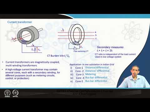
El IIT Kharagpur power system protection course treats CT principles and saturation as subjects in their own right. That is a useful reminder for procurement: a ratio describes scaling, while fault performance describes whether the measurement remains suitable for the function under the conditions being considered.
Match differential and earth-fault applications to their requirements
For a differential scheme, compare the CTs on every measured boundary and the relay’s compensation method. Ratios, polarity, secondary circuit properties and saturation behavior can affect through-fault stability. A matching primary ratio alone does not prove that the cores are suitable. Coordinate the CT selection with the actual differential function rather than finalizing each equipment item independently.
Earth-fault schemes require careful review of how residual current is obtained. A residual connection of phase CTs and a dedicated core-balance CT have different installation and measurement considerations. Identify the conductor routing and the circuit arrangement on the drawings. The protected boundary should remain clear even when cable screens, neutral conductors or multiple circuits are involved.
El substation protection zones guide is complementary: this article addresses CT selection inputs, while that guide explains how equipment boundaries divide protective duties. Review both when checking whether a CT position measures the intended circuit.
Check thermal, dynamic and insulation duties
The CT’s ability to provide a useful signal is separate from its ability to withstand the installation’s electrical duties. Confirm continuous current, short-time thermal and dynamic requirements against the fault study and switchgear specification. Verify the required insulation level and equipment voltage. A core with an appropriate protection designation can still be unsuitable if another equipment duty is not met.
Check environmental and installation conditions as well. Mounting arrangements, clearances, altitude or other specified conditions, cable or busbar geometry and terminal access should be addressed in the offered design. Do not claim that an instrument transformer is compatible with a panel solely from a photograph or a matching nominal voltage.
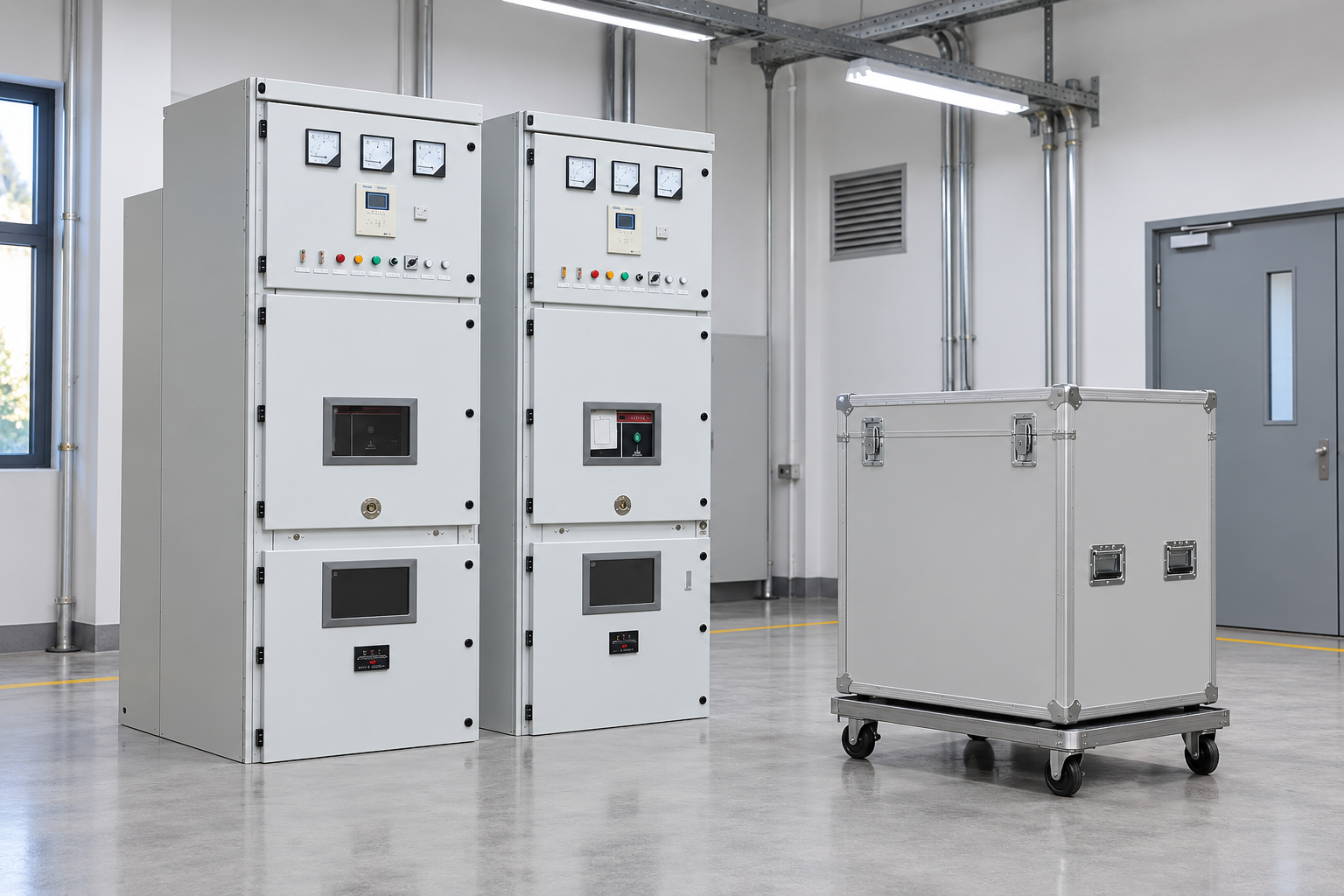
For a Shenheng medium voltage switchgear package, request the proposed CT schedule and core-specific data with the panel drawings. The cabinet illustrations establish the reference product family. They do not show a hidden CT construction or assert that every cabinet includes the same protection arrangement.
Organize the purchase review around evidence
Selection item
What the project must define
Evidence to request
Measurement boundary
Circuit and protection functions served
Single-line diagram with CT positions
Ratio and tap
Load range, sensitivity and relay scaling
Offered ratio data and selected terminal pair
Core allocation
Metering and each protective duty
Core schedule and identification markings
Installed burden
Devices, leads and test circuit
Device data and circuit calculation
Fault performance
Relevant fault currents and relay requirements
Required class, curves or transient evidence
Withstand duties
Continuous, short-time and dynamic conditions
Applicable equipment ratings and test records
Instalación
Geometry, insulation and maintenance access
Panel drawings and approved arrangements
Puesta en marcha
Ratio, polarity, circuit and function checks
Test plan tied to the installed configuration
This framework makes supplier bids easier to compare because every selection statement has a corresponding record. It avoids asking for an undefined “high quality protection CT” and then discovering at commissioning that essential data were never agreed.
Verify ratio, polarity and circuit identity before energization. Reference-based illustration.
Verify the installed circuit before relying on the relay
Acceptance starts by matching the installed CT, core and ratio tap to the approved schedule. Establish the required ratio and polarity evidence with the approved test method. Check terminal continuity and the wiring to the relay. An injection result can look reasonable while the tested circuit is a different core from the one identified in the protection study.
Review secondary grounding and test-block arrangements against the drawings. Energized CT secondary circuits must not be opened casually: approved shorting, isolation and work procedures are essential. This article is a design and acceptance guide, not a live-work procedure. The commissioning team must use equipment-specific instructions and its authorized test plan.
Prove the receiving function with appropriate injection and functional checks. Record injected quantities, relay readings, scaling, polarity assumptions and the outputs expected. A primary-circuit check may be required to demonstrate aspects that secondary injection bypasses. Identify those limits explicitly rather than using a secondary relay test as proof of the complete measurement chain.
El factory acceptance checklist helps organize supplied equipment evidence. The site acceptance checklist addresses the installed integration. Together they help prevent a factory certificate from being treated as proof that field wiring and protection configuration are correct.
Manage changes after handover
Keep a final CT schedule, marked terminal drawings, burden calculation and test record with the approved relay configuration. If a CT is replaced, compare the complete core performance and installation duties. Equivalent ratio and physical size are insufficient substitution criteria. Obtain designer approval and repeat the checks affected by the change.
Adding devices to a secondary circuit, changing lead routes or selecting another ratio tap can change the original application. A protection relay replacement can also introduce different input and CT requirements. Assess those changes before assuming the old selection remains valid. Record the new calculation basis and the tests repeated.
This is distinct from choosing a cabinet’s main short-circuit rating, which is discussed in the medium voltage switchgear overview. Both decisions use fault-study information, but one concerns the equipment assembly and the other concerns measurement and protective performance. Approve each with its own evidence.
Further learning: current transformer principles
The university lecture below explains the CT principles underlying ratio and performance review. It is educational background; project selection still requires the actual relay requirements, fault study and installed circuit information.
Further learning: Lecture 36: Current Transformer – Part – I — NPTEL IIT Kharagpur. Educational background; this is not an operating authorization. Abre el video en YouTube.
Preguntas frecuentes
Can a metering CT core be used for protection?
Only if the actual core specification and application review establish suitability for the required protective duty. Matching ratios do not make metering and protection cores interchangeable.
Why does secondary lead length matter?
Lead resistance contributes to the installed circuit burden and the voltage the CT must develop. Its significance depends on conductor size, circuit arrangement, secondary current and the protection application’s performance requirements.
Does a higher CT ratio always improve selection?
No. Ratio selection must balance load capability, protective sensitivity, relay measuring range and fault performance. A higher ratio can reduce the signal associated with a small primary current.
What must be verified after changing a ratio tap?
Confirm the selected terminals, core performance for that tap, relay scaling, protection study assumptions and affected commissioning tests. Update the controlled drawings and setting records before service restoration.
Shenheng Electric Power se compromete a convertirse en un líder mundial en soluciones de equipos eléctricos, ayudando a los clientes a lograr una gestión de energía segura, eficiente y sostenible.

 Shenheng Power Equipment Co., Ltd.