Seit 2001 ist Shenheng Power ein vertrauenswürdiger Hersteller von Energieübertragungs- und -verteilungsausrüstung und liefert weltweit zuverlässige elektrotechnische Lösungen.
Unterstützt durch ein umfassendes Kundendienstsystem bieten wir kompetente technische Beratung, Produkthinweise sowie flexible OEM- und ODM-Dienstleistungen für Ihre Projekte.
Seit 2001 ist Shenheng Power ein vertrauenswürdiger Hersteller von Energieübertragungs- und -verteilungsausrüstung und liefert weltweit zuverlässige elektrotechnische Lösungen.
Circuit breaker failure protection provides local backup when a breaker receives a valid trip command but does not interrupt the fault. The protection scheme checks whether the required interruption has occurred, then trips selected surrounding breakers if the failed breaker continues to connect the fault to its sources. For a medium voltage project, the useful question is not simply whether a relay includes a breaker failure function. It is whether the initiation, supervision, timing, trip destinations and commissioning evidence form a coordinated scheme for the actual bus arrangement. This guide explains those decisions without supplying generic settings for an energized installation.
Start with the fault path, not the relay menu
A primary protection element may detect a fault correctly while the associated breaker fails to clear it. Possible failure points include the trip supply, trip coil, mechanism, control wiring and interruption process. These are different failure modes, and a scheme that detects one condition may not detect another equally well. A breaker failure design therefore starts with the single-line diagram and the sources that could continue feeding each fault.
For a radial feeder, an upstream breaker may remove the remaining source. A bus coupler, parallel transformer or embedded generator can create additional paths. The required backup trip can consequently change with operating configuration. Mark every source and the breakers needed to disconnect it before assigning outputs in a relay configuration. The KTH power system protection lecture explains the local backup principle and why unnecessary operation has serious service consequences.
This topic complements the broader medium voltage switchgear guide. Switchgear construction establishes the physical equipment boundary; breaker failure logic establishes how protection responds when the intended switching action does not clear a fault. Neither document replaces the project protection study.
Define exactly what starts the function
The initiating signal normally comes from protection that has issued a trip to the breaker being supervised. The designer must identify each permitted initiator and its relationship to the individual breaker. A shared trip bus, transformer differential output or external protection contact can need different routing from a feeder overcurrent trip. Initiation should not be assumed merely because two functions appear in the same relay.
Specify whether manual opening, emergency shutdown, mechanical protection or external intertripping should start breaker failure logic. The answer depends on whether the scheme must cover low-current or non-electrical trips as well as faults with measurable current. Document each exception. An unexplained exclusion can leave an important failure uncovered; an unexplained inclusion can cause unnecessary backup trips during normal switching.
Initiation also needs a defined duration and reset condition. A pulse that disappears before the logic evaluates the failure can behave differently from a latched signal. Review how the particular relay handles retriggering, interrupted signals and loss of auxiliary supply. These questions belong in the functional description, where the commissioning team can turn them into test cases.
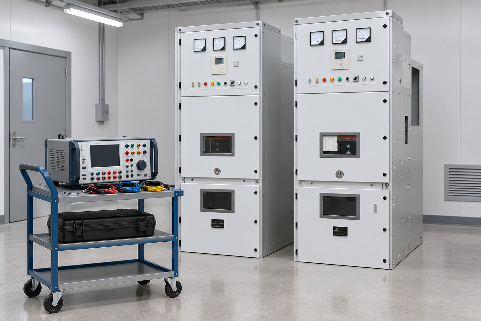
Controlled secondary injection validates the logic without proving primary interruption. Reference-based illustration.
Combine current and position evidence carefully
Current supervision asks whether current continues through the breaker after the trip command. Position supervision uses auxiliary contacts or other breaker status information. Neither is a universal substitute for the other. An auxiliary contact can indicate a mechanism position without proving that every pole has interrupted current. A current detector can be insensitive to a low-current operating condition that still requires a confirmed opening.
The protection engineer should define which evidence is required for each initiation path. Some arrangements use current as the main criterion for fault trips and separate logic for operations where current cannot be relied upon. Others combine current and position conditions. The chosen design must explain what happens when signals disagree, disappear or arrive in an unexpected order.
Check the current transformer location on the diagram. A detector measures current at its CT, not an abstract condition anywhere on the bus. Depending on topology and CT placement, current seen by one breaker can continue after another breaker opens. Commissioning must establish that the monitored current belongs to the intended breaker failure boundary. Also assess CT performance, polarity and secondary circuit integrity; a bad measurement path can undermine otherwise correct logic.
Build a timing budget from actual equipment evidence
Breaker failure delay must allow the intended breaker to clear the fault under its specified conditions, while remaining fast enough for the backup duty established by the protection study. It is not a setting copied safely from another installation. The timing review should identify breaker interruption time, protection and output delays, current detector reset behavior, signal transfer delays and an appropriate coordination margin.
Keep the timing references consistent. A relay event can report the instant of a logic output, whereas a breaker test report can measure from coil energization to a mechanical event. Adding values measured from incompatible starting points produces a misleading budget. State the start and end events for every term, and explain whether the observed time includes the output contact and trip circuit.
When a retrip stage is used, document its purpose and the relationship between retrip and the surrounding-breaker trip. A second command to the same breaker can be useful in some designs, but it must not postpone required backup clearing beyond the coordinated limit. The designer should approve the complete sequence rather than each delay in isolation. A later breaker replacement is a reason to revisit this evidence.
Use a decision table to close the design gaps
The following table is a project review aid, not a set of protection settings. Each row identifies a specific question that should have a documented answer before the scheme is accepted.
Design item
Evidence to request
Problem the review prevents
Initiation sources
Function matrix naming the breaker and permitted trip sources
Unwanted starts or an omitted protection trip
Current boundary
Single-line diagram with CT positions and operating modes
Supervising current from the wrong path
Position signals
Contact definitions, wiring drawings and disagreement behavior
Treating a status contact as proof of interruption
Timing
Equipment evidence and a coordinated sequence with clear time references
Copying an unsuitable delay
Backup destinations
Trip matrix for normal and alternate bus arrangements
Leaving a source connected or tripping unnecessary feeders
DC supply
Trip circuit drawings, supply monitoring and output requirements
A common supply failure defeating both stages
Reset and lockout
Approved logic description and restoration instructions
Repeated commands or unsafe restoration
Communications
Message mapping, supervision and failure response
An untested dependence on remote signaling
For background on current measurement and relay behavior, the IIT Kharagpur power system protection course provides an educational sequence covering CTs and protection processing. The table itself should be completed using the actual project documents and relay manual, not by treating a course example as an installation specification.
Check the trip path beyond the relay output
A successful relay indication does not prove that the correct backup breakers received usable trip commands. Follow the path through output contacts, interposing relays, terminal blocks, cables, trip coils and any communications interface. Confirm contact ratings and circuit arrangements against the approved drawings. The logic review and the physical circuit review must identify the same destinations.
Consider common causes. If the normal trip and the backup path depend on the same failed supply or damaged cable route, the scheme may have less independence than expected. Independence is a design question that must be resolved with the project requirements; it cannot be claimed just because a second relay output exists. Record what is shared and what has separate supervision.
For networked trips, check the addressing, subscribed signals, quality flags and the response to communication failure. A configuration file alone is insufficient evidence. The commissioning test should prove that the intended receiving equipment responds and unrelated equipment remains unaffected. Where an operational test could interrupt service, use the approved isolation and test facilities under a controlled commissioning plan.
Review each source path and the required backup trip destinations. Reference-based illustration.
Commission normal clearing as well as simulated failure
A useful test plan first demonstrates that a normal successful trip does not escalate into a breaker failure operation. Inject or simulate the permitted initiation, represent the expected interruption and verify reset before the backup stage. Include realistic signal order and timing around the boundary. This confirms security, which matters because a backup trip can disconnect a much larger part of the system than the original fault.
Then simulate a failed clearing condition with the approved test arrangement. Verify initiation, supervision, any retrip, the timed backup outputs and the intended reset or lockout. Repeat for different initiators and operating modes where the logic differs. A single forced output test proves only that output, not the whole function.
Add negative cases: current without a valid initiator, initiation without the required supervision, inconsistent position contacts, interrupted initiation and a unavailable communication path where applicable. Record expected and observed behavior for every case. Secondary injection does not prove primary breaker interruption performance, so combine its results with the appropriate breaker and trip circuit evidence. The factory acceptance checklist helps organize equipment evidence; the site acceptance checklist addresses the installed circuit and integration boundary.
Specify the complete package when purchasing switchgear
For a project using Shenheng medium voltage switchgear, include the breaker failure requirements in the protection and control specification. Ask for the proposed relay function allocation, CT arrangement, auxiliary contact definitions, trip circuit drawings and test facilities. The product photograph illustrates the equipment family; it does not establish the installed relay type or a particular protection configuration.
Request the editable logic and setting records, the approved trip matrix, version identification and test reports in the handover package. Clarify which party approves the protection study and which party is responsible for field integration. A supplier can assemble a panel to a drawing without owning the network-wide coordination assumptions. Those responsibilities need to be explicit before acceptance.
Retain a baseline configuration after commissioning. Changes to generators, bus ties, transformer arrangements, CTs, trip supplies or communications can affect the scheme even if the feeder relay itself is untouched. The maintenance record should connect each approved change to the tests repeated and the documents revised. That makes future troubleshooting evidence-based rather than dependent on recollection.
Further learning: relay testing and commissioning
The following university lecture supports the testing discussion. Use it to understand how commissioning establishes relay behavior; the article and approved project documents remain the basis for the specific breaker failure test matrix.
Further learning: Lecture 40 Testing, Commissioning and Maintenance of Relays-II — IIT Roorkee July 2018. Educational background; this is not an operating authorization. Öffne das Video auf YouTube.
Häufig gestellte Fragen
Is breaker failure protection the same as backup overcurrent protection?
No. Breaker failure protection is initiated by a defined trip operation and checks whether the associated breaker cleared the condition. Backup overcurrent protection responds to its own current and timing criteria. Their duties can overlap, but their initiation, selectivity and coordination need separate review.
Can a breaker open indication prove that the fault is cleared?
An auxiliary contact alone does not prove interruption in every relevant situation. The scheme must use the approved current and position criteria for the breaker and operating condition, including the intended response when those signals disagree.
What delay should a medium voltage breaker failure function use?
Use a delay approved by the protection study and supported by actual breaker, trip circuit and relay evidence. There is no universally safe value for all medium voltage installations. Define consistent time references and check the full backup clearing sequence.
What should the commissioning report include?
Include the tested configuration version, initiation sources, monitored signals, timing references, expected and observed outputs, trip destinations, negative cases and restoration checks. Identify any part of the primary interruption or remote trip path that was not proven by the test.
Shenheng Electric Power hat sich zum Ziel gesetzt, ein weltweiter Marktführer für Lösungen im Bereich Energieausrüstung zu werden und Kunden dabei zu helfen, ein sicheres, effizientes und nachhaltiges Energiemanagement zu erreichen.

 Shenheng Power Equipment Co., Ltd.