
 شركة شنغهنغ لعدات الطاقة المحدودة.



Substation surge arrester selection and placement must match system grounding, continuous operating voltage, temporary overvoltage, insulation coordination, transformer terminals, cable layout and the earth connection. The correct arrester in the wrong location or with long unrestrained leads may not protect the equipment as intended.
Surge arrester placement
Surge arrester selection and placement depend on system grounding, continuous operating voltage, temporary overvoltage, insulation coordination, transformer terminals, lead length and earth connection. A correct arrester in the wrong location may not protect the equipment as intended.
Coordinate arrester MCOV, energy duty, line and earth leads, clearances and discharge path with the transformer and cable layout. Keep leads short and mechanically supported, and verify the ground connection and inspection access in the as-built record.
Build the arrester selection from the system voltage
Start with the voltage that the arrester will continuously experience at its terminals. In a phase-to-earth application, this is tied to the actual system operating voltage and grounding arrangement, not simply the equipment’s line-to-line nameplate voltage. Establish the highest expected operating voltage and obtain the system’s temporary-overvoltage conditions, including their durations. Select the continuous-voltage capability and check the manufacturer’s temporary-overvoltage curve together. A device that appears suitable during normal operation may be unsuitable during an earth fault or another sustained abnormal voltage condition.
Next compare protection with the insulation of the equipment being protected. Obtain the arrester’s protective characteristics for the specified duties and the transformer’s or switchgear’s applicable insulation withstand information. Include the installation arrangement in that review. Long or poorly routed connecting leads can add voltage during a steep-front surge and reduce the practical protection achieved at the equipment terminal. The arrester should therefore be placed with a short, direct connection path consistent with the approved clearance and earthing design. Do not infer installation effectiveness solely from a catalog residual-voltage value.
Review energy and environmental requirements independently of the voltage choice. The credible lightning and switching duties depend on the network and its operating conditions. Housing, pollution performance, mechanical loading, altitude and access requirements also need to match the installation. Specify the actual mounting position and connection arrangement so the delivered unit can be installed without improvised lead extensions. Where a counter or condition-monitoring accessory is included, confirm how it fits into the earthing path and how readings are interpreted using the supplied instructions.
For acceptance, retain the system-voltage assumptions, grounding description, temporary-overvoltage assessment, selected device characteristics and insulation-coordination review. Check the delivered identification against that package, then inspect mounting, clearances, lead routing and earth connections under an approved safe condition. Photograph the finished arrangement for the as-built record. Damage, leakage-current concerns or an unusual counter reading should trigger the manufacturer’s investigation procedure rather than an unsupported replacement decision. This guide does not provide a universal arrester voltage or energy rating; those values must come from the project study and the specified manufacturer’s evidence.
Distinguish continuous voltage from a transient duty
The arrester must tolerate the voltage continuously present at its terminals while providing protection against the relevant transient stresses. Rated voltage and continuous operating voltage are distinct terms, and the chosen values need to match the actual application. A nominal network voltage on its own is not a complete selection basis.
The designer should identify the system’s maximum operating condition and how phase-to-earth voltage behaves for the applicable grounding arrangement. Confirm the values and terminology used in the supplier’s data sheet. Do not choose an arrester by matching the biggest printed voltage number to the transformer’s nameplate without checking what each number represents.
Review temporary overvoltage separately
A temporary power-frequency overvoltage is different from the fast surge the arrester is intended to limit. Its magnitude and duration need a separate engineering assessment. Ground faults, operating conditions and the network’s grounding arrangement can affect that assessment; the actual scenarios come from the project’s electrical study.
Request the supplier’s applicable temporary-overvoltage capability and the conditions behind it. Compare the design scenario with the declared capability, including any relevant assumptions. An arrester with a protective level that looks attractive may still be unsuitable if it cannot withstand the project’s temporary voltage duty. Selection must reconcile both questions instead of optimizing one characteristic alone.
Relate the protective level to the protected insulation
The protection objective depends on the equipment insulation and the voltage that can reach its terminals. The arrester’s declared protective characteristic forms part of that assessment. The designer must also consider the connection arrangement and the applicable coordination margin, rather than assuming that the catalog characteristic appears unchanged at every remote point in the installation.
A transformer, switchgear assembly and cable system can present different interfaces. Identify which equipment is being protected and obtain the relevant insulation information. Where those data are missing, the selection should remain conditional until the required evidence is available. The arrester supplier’s generic product class cannot fill an undocumented equipment withstand value.
Place the arrester with the actual connection path in mind
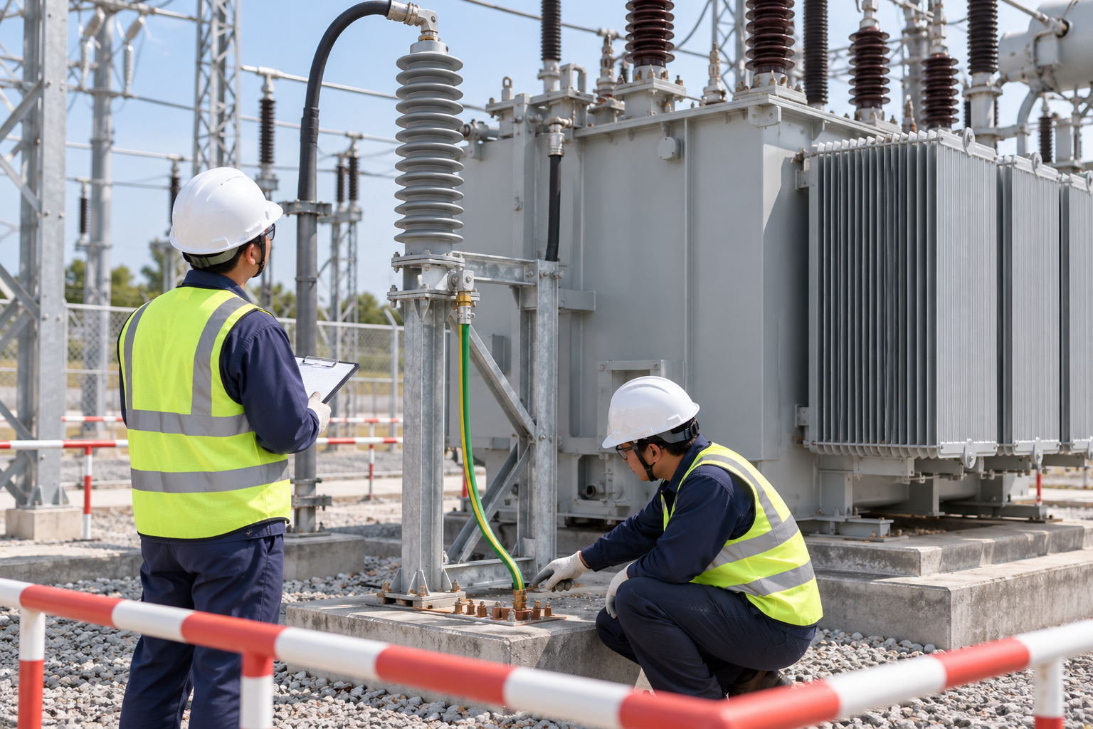
The location and connection route influence how protection reaches the equipment. Review the line connection, earth connection and their relationship to the protected terminals. A physically nearby arrester is not automatically well connected if the conductors follow a long or indirect route.
The approved arrangement should seek appropriately short and direct connections while maintaining required clearances, mechanical support and safe access. Avoid proposing an exact universal lead length from a general article. The relevant project study, installation instructions and site geometry determine the acceptable arrangement. Check the final route after installation rather than relying only on the tender drawing.
Check energy and repeated-surge duty
An application can involve more than one transient scenario. The specification should identify the relevant surge duty and the information the manufacturer needs to assess capability. Do not treat a single discharge-current figure as proof of suitability for every energy exposure or operating sequence.
The engineering team and supplier should agree which declared characteristics address the project duty and which supporting evidence is required. If a network change alters the transient exposure, review the original selection. A replacement chosen solely because it fits the mounting holes may have different electrical capabilities that are material to the protection objective.
Include environment and mounting constraints
Confirm the pollution conditions, altitude, mechanical loads and enclosure or outdoor arrangement relevant to the site. Ask the supplier how the proposed housing, insulation and mounting meet those requirements. A unit suitable for a clean indoor application should not be assumed suitable for an exposed installation without review.
The layout also needs inspection and replacement access. Record any required orientation, support arrangement and accessories from the actual manufacturer instructions. If a surge counter or monitoring device is included, check its role and connection requirements. The accessory should not be added through an improvised arrangement that changes the intended earth path or creates an undocumented maintenance hazard.
Use the applicable selection and test references
IEC 60099-4 addresses metal-oxide surge arresters without gaps for alternating-current systems. IEC 60099-5 provides selection and application guidance. Confirm the standard and edition required by the project and request the corresponding declared product information.
A standards reference is a framework for evaluation, not evidence that an unspecified arrester has already been selected for the site. The supplier should identify the actual model, continuous-voltage capability, temporary-overvoltage information, protective characteristics and relevant duty declarations. Keep that evidence with the approved insulation-coordination review.
Turn the study into an installation inspection
At site, reconcile the delivered model and nameplate with the approved selection. Check that the intended equipment and connection points match the released drawing. The responsible inspection team should confirm the mounting, visible condition, clearances and line and earth routes under the applicable installation procedure.
Record deviations with photographs and identify whether they affect the protection assessment. Moving an arrester to simplify a cable route should not be treated as an unreviewed cosmetic change. An approved correction may require revised drawings and a repeat of the affected inspection. Do not energize solely because the accessory has been physically mounted and its paperwork is present.
A transformer-terminal placement example
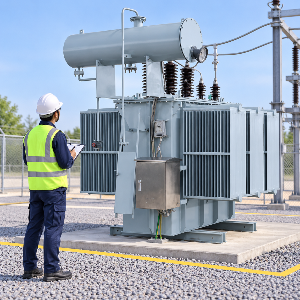
Consider a hypothetical project where an arrester initially sits near the transformer on the design drawing. During installation, a different cable route produces a longer connection path than the reviewed arrangement. The inspection team records the actual route and refers the change to the designer rather than assuming that the unchanged arrester model preserves the original protection outcome.
The designer reviews the revised arrangement with the relevant equipment data and supplier information. The decision may require relocation, a connection change or documented acceptance of the assessed configuration. This example provides no invented protective margin or conductor length; the actual geometry and electrical study determine the result.
Preserve a usable maintenance baseline
The handover file should contain the selected model, approved study, installation drawing, inspection photographs and the instructions for the supplied arrester and accessories. Record the baseline observations for any monitoring features included. A counter reading alone does not establish that the arrester or protected transformer is healthy.
After a significant event or a network modification, the responsible team should decide whether inspection or a selection review is needed. Replacement records should identify the electrical characteristics as well as the physical model. Keeping the protection objective and connection arrangement documented helps prevent a future maintenance substitution from weakening the original design.
Organize the selection evidence
| Selection question | Information required | Review outcome |
|---|---|---|
| Continuous voltage | System maximum condition and grounding arrangement | Confirm the applicable continuous-voltage capability |
| Temporary overvoltage | Assessed magnitude, duration and supplier capability | Establish compatibility for the actual scenario |
| Insulation coordination | Equipment insulation and protective characteristics | Confirm the project protection assessment |
| Surge duty | Relevant transient exposure and declared capability | Identify suitability and unresolved assumptions |
| Placement | Line and earth routes at the protected equipment | Approve the actual installed arrangement |
| Environment | Pollution, altitude, mechanical and mounting conditions | Confirm the supplied construction fits the site |
Use this qualitative checklist with the project study and manufacturer information; it supplies no invented numerical acceptance limits.
دليل المنتجات والتكنولوجيا ذات الصلة
للحصول على سياق المنتج Shenheng المطابق، راجع 35KV MV&HV Oil Immersed Industrial Power Transformer. بالنسبة للموضوع الأوسع، اقرأ نظام التأريض في المحطات الفرعية: تصميم الشبكة، جهد اللمس، والاختبار. قراءة ذات صلة: Substation Insulation Coordination Explained و Substation Lightning Protection Design.
المصادر والمعايير
IEC 60099-4: Metal-oxide surge arresters · IEC 60099-5: Surge-arrester selection and application
صورة فيديو للبيئة النظامية
This neutral Practical Engineering explainer gives background on substations, transformers and switchgear. It is educational context, not a switching or test instruction.
الأسئلة الشائعة
Is nominal system voltage enough to select an arrester?
No. Review continuous operating voltage, temporary-overvoltage duty, protective characteristics, grounding and the actual application.
Why does placement matter?
The line and earth connection paths influence the voltage protection at the equipment. Review the final location and conductor route against the approved arrangement.
Can a mounting-compatible arrester replace the original?
Physical fit is insufficient. Confirm the replacement electrical capabilities and application evidence before approving the substitution.
Does a surge counter prove that the protected transformer is healthy?
No. It supplies a limited observation and cannot replace the applicable inspection and transformer-condition assessment.




