شركة شنغهنغ لعدات الطاقة المحدودة.
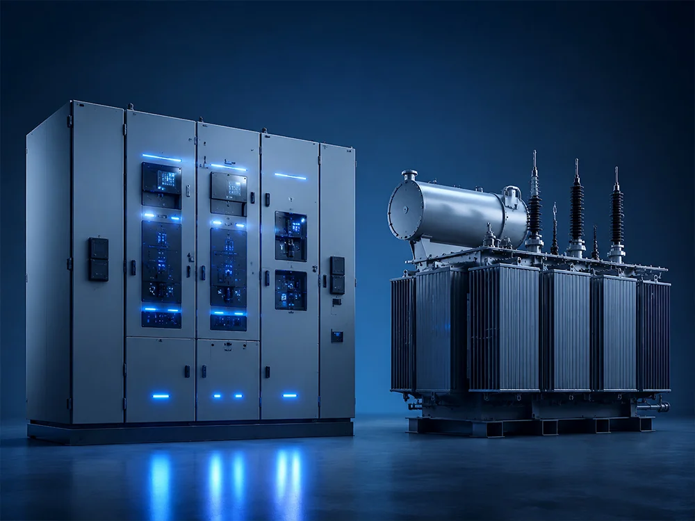


اختبار كابلات وحدة الشبكة الرئيسية هو التحقق المسيطر عليه من دائرة كابل جهد متوسط متصل أو معد للاتصال بوحدة الشبكة الرئيسية (RMU). قد يشمل نطاق الاختبار استمرارية الموصل، تحديد الطور، فحوصات العزل أو الغطاء، واختبار مقاومة أو اختبار تشخيصي معتمد. تعتمد الطريقة الصحيحة على نوع الكابل، فئة الجهد، العمر، الملحقات وكل شيء متصل بـ RMU. يجب أن يتم التخطيط للاختبار بالتنسيق مع مصنعي الكابلات، والنهايات، ومعدات المفاتيح، ويجب أن ينفذه أفراد مؤهلون على معدات معزولة، ومختبرة كميتة، ومؤرضة.
حدد السؤال قبل اختيار الاختبار
يستفسر اختبار قبول الكابل الجديد عما إذا كانت هناك أضرار في التركيب أو عيوب في الصنع قبل التشغيل. يختبر اختبار الصيانة ما إذا كانت الأصول أثناء الخدمة تظهر تدهورًا أو تغييرًا كبيرًا. يحدد نشاط تحديد الموقع العطل مكان العيب المعروف. تستخدم هذه الأهداف معدات وتفسيرات مختلفة.
حدد مسار الكابل، الطول، حجم الموصل، العزل، شاشة وبناء الغطاء، الوصلات، النهايات، والجهد التشغيلي. سجل نوع، طراز، جهد التصنيف، ترتيب حجرة الكابل، وصول الاختبار، والأجهزة المتصلة بـ RMU. لــ وحدة الشبكة الرئيسية شنهنغ, اطلب الرسم الهندسي الخاص بالمشروع ودليل التشغيل بدلاً من افتراض أن جميع نقاط اختبار الكابل لها تصنيفات أو أقفال متطابقة.
المعايير والحدود التي يحددها المصنع
يغطي IEC 60502-2 كابلات الطاقة ذات العزل المفرغ وملحقاتها للأنظمة من 6 كيلوفولت حتى 30 كيلوفولت، بينما يتناول IEC 62271-200 مفاتيح التوصيل المعدني ذات التيار المتردد فوق 1 كيلوفولت وحتى 52 كيلوفولت. تتوفر نطاقاتها الرسمية من IEC 60502-2 و IEC 62271-200. استخدم إصدارات العقد، واللوائح المحلية، ووثائق المصنع للقيم والإجراءات الفعلية.
قد يتم أيضًا تحديد أدلة IEEE 400 لعائلة الاختبار الميداني لنظم كابلات الطاقة المحمية. يجب أن يوضح المشروع أي طريقة تحكم. لا تدمج جهدًا من معيار واحد مع مدة من آخر. الملحقات، عمر الكابل، والهدف التشخيصي مهم. قد لا يكون الاختبار المناسب لكابل XLPE جديد مناسبًا لدائرة مختلطة قديمة أو لمعدات لا تزال متصلة في الطرف الآخر.
| اختبار أو فحص | الغرض | الحذر في التخطيط |
|---|---|---|
| استمرارية وتحديد الطور | تأكيد مسار الموصل وتسميات الطور | منع القراءات الخاطئة من خلال المسارات الموازية |
| مقاومة العزل | فحص الحالة الأساسية والعيوب الإجمالية | ليس دليلاً كاملاً على حالة كابل MV |
| سلامة الغلاف الخارجي | اكتشاف التلف في الغلاف الخارجي الزائد | عزل التوصيل وحماية الملحقات حسب المواصفات |
| تحمل التيار المتردد VLF | التحمل عند القبول أو الصيانة حيثما تم الموافقة عليه | الجهد، شكل الموجة والمدة تعتمد على الكابل |
| دلتا تان أو التفريغ الجزئي | معلومات التشخيص والاتجاهات | يتطلب معدات مناسبة وتفسير خبير |
| تحديد موقع العطل | تحديد عيب مؤكد | يجب أن تتجنب الطاقة والطريقة الضرر غير الضروري |
العزل والإعداد الآمن
استخدام برنامج التبديل المعتمد لتحديد جميع المصادر الممكنة، بما في ذلك التغذية العكسية، التوليد المدمج والجهد المستحث. فتح أجهزة التبديل الصحيحة، تأمينها تحت نظام قفل الموقع، إثبات كاشف الجهد، التحقق من عدم وجود جهد وتطبيق التأريض وفقًا لقواعد السلامة. تساعد مخططات محاكاة وحدة المفاتيح الآلية والمؤشرات الميكانيكية، لكنها لا تحل محل التحقق من الجهد. تعامل مع آليات التحكم عن بعد والطاقة المخزنة كمخاطر إضافية.
يجب أن يكون حد الاختبار مرئيًا على مخطط الخط الواحد. قرر ما إذا كان الكابل لا يزال متصلًا بنقطة اختبار وحدة المفاتيح، أو غير متصل عند النهاية، أو معزول بترتيب مصمم خصيصًا. تحقق من تصنيف مقابس الاختبار والواجهات. قم بإزالة أو عزل مانعات الصواعق، مؤشرات الجهد، محولات الأجهزة والإلكترونيات الحساسة عندما يتطلب الإجراء المعتمد ذلك. في النهاية البعيدة، امنع الوصول وتأكد من هوية الكابل نفسها.

تسلسل الاتصال والاختبار
- عقد إحاطة قبل الاختبار المسبق. مراجعة الهدف، هوية الدائرة، الحدود، المخاطر، الاتصالات ومعايير التوقف.
- فحص الدائرة. التحقق من النهايات، أسلاك الربط، نقاط الاختبار، معلومات مسار الكابل والأضرار الظاهرة.
- التحقق من العزل. إكمال قفل التيار، التحقق من غياب الجهد، التأريض وعزل التحكم وفقًا لإجراء الموقع.
- تكوين الحد. فصل أو حماية المعدات غير المشمولة في الاختبار وتأمين الطرف البعيد.
- الاتصال مع تطبيق التأريض. استخدام أسلاك مصنفة، حواجز وأجهزة تفريغ؛ ثم إزالة فقط التأريض المطلوب بواسطة طريقة الاختبار المعتمدة.
- إجراء الاختبار المحدد. تسجيل شكل الموجة، الجهد، المدة، التسرب أو بيانات التشخيص وأي انقطاعات.
- Discharge and re-ground. Cables can retain charge; follow the tester and cable procedure before approach.
- Restore the system. Remove test connections, reinstate bonding and accessories, check hardware and complete the switching program.
No single sequence can replace the site procedure. Long cables can store substantial energy, and adjacent energized circuits can induce voltage after a test. Grounding and discharge time must be based on the circuit and equipment, not on an informal waiting period.
Choosing between withstand and diagnostic methods
A withstand test applies a specified electrical stress and produces a pass or breakdown result under defined conditions. A diagnostic test measures properties such as dielectric loss or partial-discharge behavior to support condition assessment. Passing a diagnostic threshold is not automatically equivalent to passing a withstand test, and a single diagnostic value should not be interpreted without cable construction, temperature, length, history and baseline data.
For new extruded cable, VLF AC may be specified where compatible with the cable and accessories. For aged circuits, the owner may prefer a lower-risk diagnostic program or a carefully selected maintenance withstand. DC testing should not be assumed acceptable for every extruded-insulation system. The test provider should cite the governing document, explain the selected stress and confirm compatibility with the RMU interface and connected terminations.
Interpreting results
First check data quality: correct cable length, stable connections, calibrated equipment, environmental conditions and absence of parallel paths. Then apply the acceptance criteria defined before testing. Leakage current alone can be misleading because circuit capacitance, surface contamination and temperature influence the reading. Partial-discharge location plots require expertise to separate real cable or accessory signals from noise and reflections.
If a test stops or indicates a defect, keep the circuit isolated and grounded. Do not repeatedly reapply voltage merely to obtain a pass. Review the event, inspect terminations and joints, verify test configuration and agree on fault-location or repair actions. After repair, repeat only the approved scope and document the as-left condition. Link results to the specific cable ID so future trending compares the same asset.
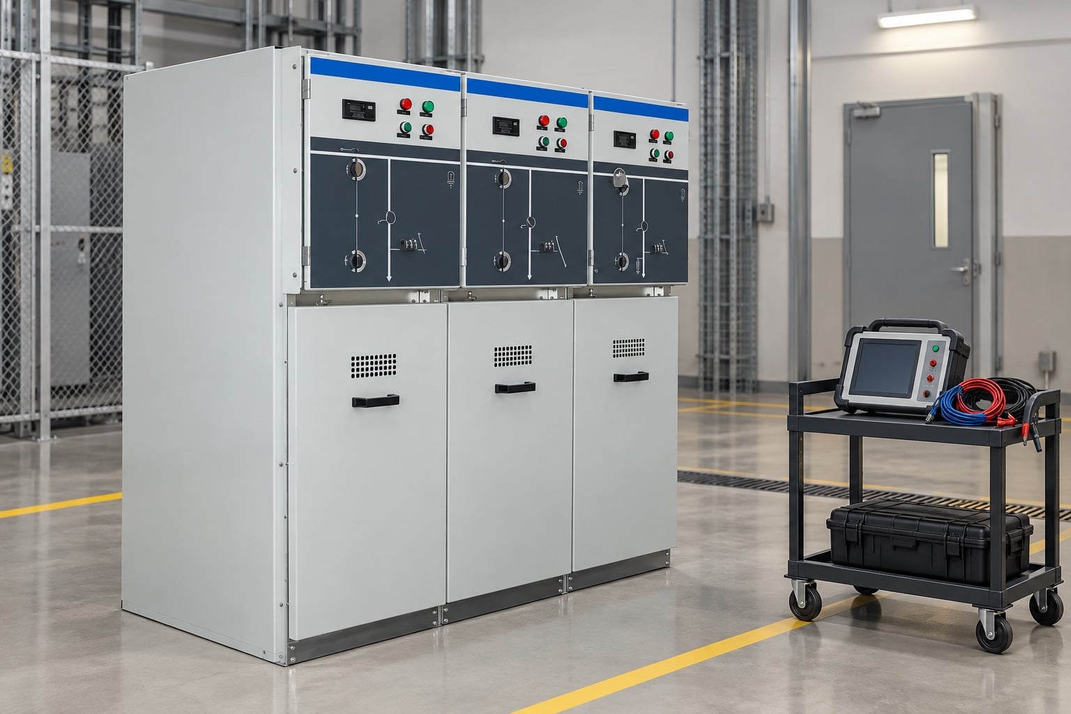
RMU-specific mistakes to avoid
- Assuming the earthing switch position alone proves the cable is safe.
- Applying test voltage through a voltage indicator or surge arrester not rated for it.
- Using a test plug that fits mechanically but lacks the required electrical rating.
- Forgetting a remote source, parallel feeder or connected transformer.
- Leaving screen bonds, grounds or disconnected links in the wrong final state.
- Closing a cable compartment before completing a tool and debris check.
- Recording only “pass” without voltage, duration, waveform, circuit ID and instrument details.
Operating configuration also matters. The 3-way versus 4-way RMU guide explains feeder-count differences, while the extensible versus non-extensible RMU guide covers future lineup changes. Use the actual panel schedule to identify the feeder under test.
Test report checklist
A complete report records owner, site, circuit ID, cable endpoints, cable and accessory data, RMU section, test objective, governing document, instrument model and calibration, environmental conditions, isolation boundary, test connections, waveform, voltage, duration, readings, acceptance criteria and result. Include anomalies, interrupted tests and repairs rather than presenting only successful values. Signatures should identify the tester and approving engineer under the quality plan.
Before return to service, use an independent restoration check: correct phase identification, screen bonding, termination hardware, test-point caps, shutters, interlocks, earth-switch position, cable-compartment covers and remote-end status. Confirm protection and control availability. The operations team, not the test instrument, authorizes energization.
Building a repeatable maintenance program
Repeat tests are valuable only when the circuit identity, configuration, method and data quality remain comparable. Create a test register that links each result to the cable route, joints, termination replacements and operating events. Trend diagnostic data with the same units and correction method, and preserve raw files rather than only a summary. Review the program after faults, network changes or manufacturer advisories. Testing frequency should follow asset criticality, condition, environment and owner policy; it should not be increased automatically because one result is difficult to interpret. A sound program combines inspection, operating history and protection records with electrical testing, then uses qualified engineering judgment to decide whether to return, monitor, repair or replace the circuit.
Video: how RMUs fit into the substation
This independent substation overview provides context for switching and protection. It is not a cable-test instruction and does not define test voltage.
الأسئلة الشائعة
هل يمكن إجراء اختبارات الكابلات من خلال وحدة توزيع كهربائية (RMU)؟
Only where the RMU provides an approved, correctly rated test interface and the manufacturer procedure defines the configuration.
هل مقاومة العزل كافية لقبول كابل الجهد المتوسط؟
No. It is a useful basic check but does not replace the project-specified withstand or diagnostic test.
هل يجب أن تظل أجهزة الحماية من الارتفاعات متصلة؟
Follow the approved system procedure. Arresters and other devices may need isolation because the cable test voltage can be unsuitable for connected equipment.
ماذا يجب أن يحدث بعد الاختبار؟
Discharge and re-ground the cable, restore all bonds and devices, complete an independent configuration check and retain the full test record.