Shenheng Power Equipment Co., Ltd.
- Home
- Products
Products
Since 2001, Shenheng Power has been a trusted manufacturer of power transmission and distribution equipment, delivering reliable electrical solutions globally.

- Solutions
- News & Blog
- Service
- About Us
- Contact Us
Since 2001, Shenheng Power has been a trusted manufacturer of power transmission and distribution equipment, delivering reliable electrical solutions globally.
The Buchholz relay working principle uses gas accumulation and oil movement to detect abnormal conditions in a conservator-type oil-filled transformer. Gas collecting in the relay can lower the oil level and operate an alarm element; a sufficiently rapid oil surge toward the conservator can operate a trip element. The exact mechanisms and settings depend on the relay design. An alarm does not identify the fault by itself, and a trip is not permission to reset and re-energize. This guide explains the protection concept, its application limits and the evidence needed to interpret an event safely.
A conventional Buchholz relay is installed in the oil pipe between the transformer main tank and its conservator. That location allows gas moving out of the main tank to collect in the relay and allows the relay to respond to relevant oil movement. Correct pipe geometry, orientation and installation are therefore part of the protection function.
The US Bureau of Reclamation transformer manual explains gas-actuated protection in the context of transformer maintenance and diagnostics. Use it as technical background alongside the specific relay and transformer instructions. It does not make every transformer or relay arrangement interchangeable.
This application is different from a fully sealed transformer without an external conservator. Other gas, pressure or oil-level protection arrangements may be used, but they should not be called a conventional Buchholz installation simply because they also monitor oil-related conditions. The sealed versus conservator transformer comparison helps establish that boundary.
The relevant product family is the 35 kV oil-immersed power transformer. Its visible conservator arrangement provides useful context for this article. A product photograph cannot prove a particular relay model, setting or project protection scheme; those require the order drawings and supplied documentation.
Under normal conditions, the relay housing is filled with oil. Gas reaching the relay can collect at its upper part and displace oil. In a typical double-element design, the changing oil level moves the upper float mechanism until its contact changes state. The associated circuit reports an alarm according to the approved scheme.
Gas formation can be associated with internal heating or insulation deterioration, but air introduced during maintenance or filling can also be relevant. The relay detects a physical condition; it does not perform gas analysis or identify the affected winding. Event interpretation must therefore combine the relay evidence with the transformer history and other observations.
A developing event may produce an alarm without an immediate surge trip. That does not make the event harmless. Review the operating instructions and site response procedure, preserve evidence and obtain a qualified assessment. Do not leave the transformer in service simply because a trip contact has not operated.
Avoid using a generic gas-volume threshold from another relay. Housing size, element arrangement and specified operating values differ. Record the model and approved settings before drawing conclusions about what an alarm means on a particular installation.
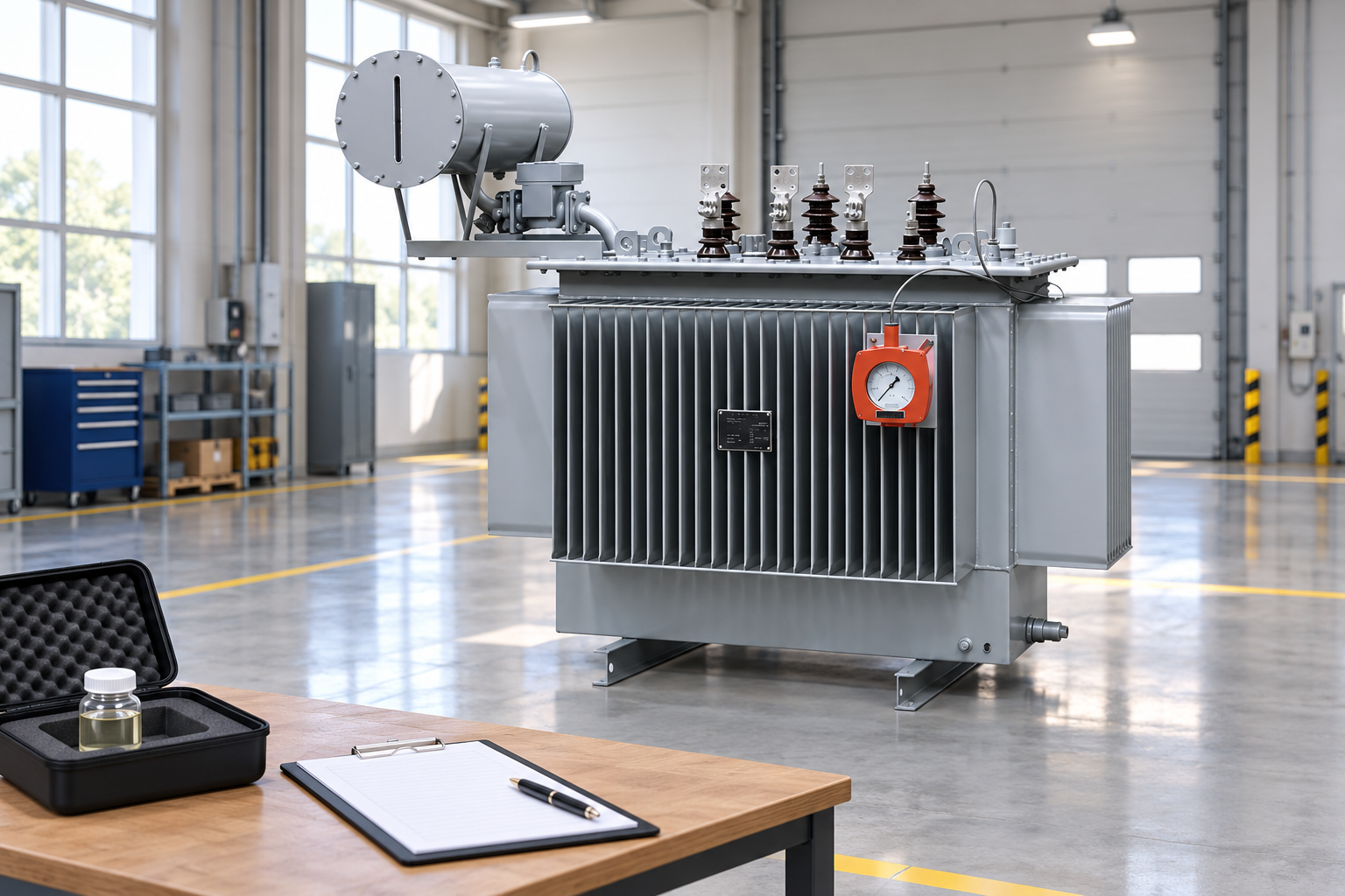
An internal disturbance can produce rapid oil movement toward the conservator. A conventional relay uses a lower element or flow-sensitive mechanism to respond when movement reaches the specified operating condition. Depending on the design, a float, flap or associated mechanism changes the trip contact state.
The trip contact must connect to an effective protection path. The physical relay alone does not open the circuit breaker: its signal passes through the installed wiring and any intermediate logic or relays to the designated interrupting devices. The complete chain must be documented and functionally verified.
Relay orientation and flow direction matter. Installation that contradicts the manufacturer’s instructions can change the intended response. Pipework and isolation arrangements also need review. Do not infer correct installation merely because the relay is visibly located near the conservator.
The actual trip circuit may include latching or lockout functions. Its behavior after an event belongs to the approved protection design. A local indication clearing does not necessarily mean the transformer is released for service, and resetting an associated lockout is an operating decision with separate requirements.
Use the first event record to establish which contact operated and when. Preserve alarm timestamps, breaker indications, protection records and the operating conditions immediately before the event. A delayed investigation can lose the sequence needed to distinguish a primary event from a consequence.
| Observation | What it can indicate | Evidence needed before a conclusion |
|---|---|---|
| Gas alarm | Gas collection or changing oil level at the relay | Relay indication, gas evidence and maintenance history |
| Surge trip | Operation of the flow-sensitive element | Event sequence, contact state and protection records |
| Low oil indication | A relevant oil-level condition | Level readings, leakage observations and temperature context |
| Alarm after oil work | Air or another condition following maintenance | Filling records, approved checks and specialist assessment |
| Multiple protection operations | A wider electrical or mechanical event | Disturbance records and coordinated investigation |
| No relay operation | No detected operating condition at this device | Other protection and diagnostic evidence remain necessary |
This qualitative table does not prescribe continued operation, reset or energization. It helps structure the information sent to the responsible transformer specialist.
Separate Buchholz evidence from dissolved gas analysis. One detects a condition in the relay path; the other measures gases in an oil sample. They can support the same investigation but do not provide identical information. Sampling and interpretation require the appropriate methods and context.
Review whether the transformer was recently filled, topped up, filtered, transported or opened. Relevant maintenance can introduce conditions that affect the relay, but it must not become an automatic explanation for an alarm. Record what work occurred and what acceptance checks were completed afterward.
Oil temperature and conservator behavior can affect observed levels. Use the supplied level indication instructions and the actual operating conditions. A reading compared with the wrong temperature basis can lead to an incorrect diagnosis of low oil or overfilling.
Check for visible leakage from safe, authorized positions. The transformer oil leak guide addresses a related physical issue. Inspection should not involve opening energized equipment or disturbing the relay simply to obtain a better view.
Gas collection and sampling should follow an approved procedure performed by qualified personnel. Do not use a flame test or an improvised venting method. The purpose is to preserve meaningful evidence while controlling pressure, electrical and environmental hazards.
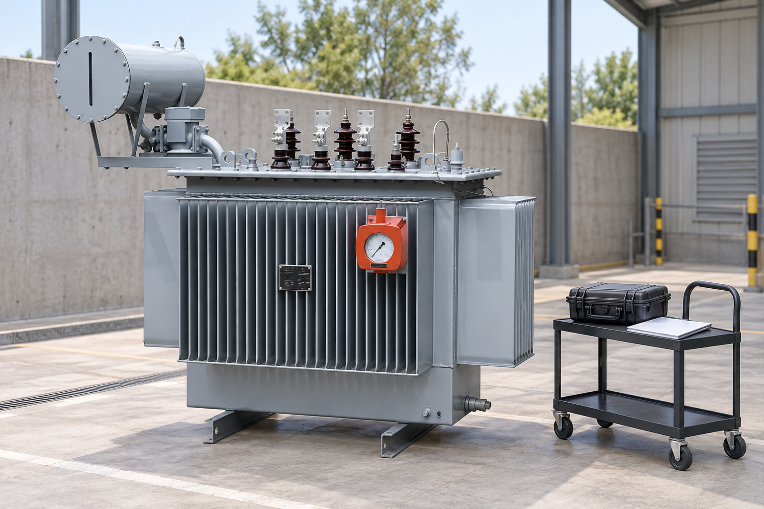
The protection review should identify relay contacts, terminal numbers, cable references, intermediate devices, alarm destinations and the breakers intended to trip. Reconcile these with the actual installation and the current approved drawings. A contact labeled correctly on one drawing can still be connected incorrectly in the field.
Functional verification needs a controlled test boundary and an approved method. The Bureau of Reclamation transformer maintenance guide provides maintenance background. The supplied equipment instructions and site procedures determine the actual test method and interval. Do not copy a test action from an unrelated relay model.
Include the final alarm and trip destinations where the approved test scope requires them. A continuity check at the relay terminals is not the same as demonstrating that the control room receives the correct alarm or that the designated breaker trip circuit operates.
Preserve test results and restored conditions. Temporary test links, bypasses and disconnected circuits require explicit control and verification before release. A completed test report should state both what was tested and what was deliberately outside the boundary.
Buchholz protection is associated with the oil and gas path of the relevant transformer arrangement. It does not replace differential protection, overcurrent protection, temperature monitoring or other specified functions. Some faults may not produce the conditions required to operate this relay.
A lack of gas alarm therefore does not prove that the transformer is healthy. Likewise, an alarm alone does not locate a winding fault or establish its severity. Evaluate the complete evidence set and the protection design rather than treating a single indication as a comprehensive diagnostic result.
The relay also does not independently verify that its external wiring is intact or that trip power is available. Those questions belong to the complete protection system. Monitoring and maintenance arrangements should reflect the consequences of a failed signal path.
Keep scope clear in procurement documents. Specify the transformer arrangement, required protective functions and interfaces, then obtain the supplier’s proposed equipment and drawings. Do not order a relay by a familiar name without confirming its intended application and compatibility.
A useful event package includes the transformer identity, relay model, approved settings, alarm and trip sequence, loading history, recent maintenance and relevant oil or gas test records. Include photographs taken safely and any available disturbance records from other protection devices.
State whether the transformer remained energized, was tripped or was isolated under the operating procedure. Record actions already taken so the reviewing specialist can interpret subsequent observations correctly. Avoid altering evidence solely to clear a visible alarm.
After an investigation, retain the decision basis for repair, testing and return to service. Any changed setting, replaced relay or revised circuit should be reflected in the drawings and maintenance records. The goal is a documented protection function and a justified operating decision, not simply the disappearance of an indication.
Tracing Science’s animation shows the conservator connection and the physical response concept. It is an educational illustration, not a model-specific installation or testing instruction. Compare the general mechanism with the documentation supplied for the actual equipment.
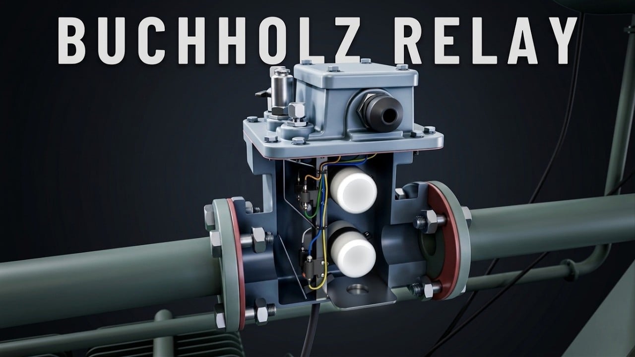
Further learning: What is Buchholz relay? | 3D Animation #transformers — Tracing Science. Educational background; this is not an operating authorization. Open the video on YouTube.
No. A conventional Buchholz relay is associated with the pipe between a main tank and an external conservator. Fully sealed arrangements may use different protective devices and need their own application assessment.
Gas-related evidence can have more than one cause, including relevant conditions after maintenance. Preserve the event information and obtain a qualified interpretation rather than assuming either a fault or harmless trapped air.
A trip requires the approved investigation and operating process. Clearing an indication or resetting a device does not establish that the transformer is safe to re-energize.
No. The functions respond to different conditions and form parts of a coordinated protection scheme. Their application and signal paths should be documented and verified separately.