
 Shenheng Power Equipment Co., Ltd.
- Home
- Products
Products
Since 2001, Shenheng Power has been a trusted manufacturer of power transmission and distribution equipment, delivering reliable electrical solutions globally.

- Solutions
- News & Blog
- Service
- About Us
- Contact Us
Since 2001, Shenheng Power has been a trusted manufacturer of power transmission and distribution equipment, delivering reliable electrical solutions globally.
Transformer neutral grounding defines how a system neutral is connected to earth and how that connection influences earth-fault current, voltage conditions and protective response. The main choices include solid grounding, resistance grounding, reactance grounding and arrangements with no intentional neutral-to-earth connection. The right method depends on the network, transformer winding configuration, insulation requirements, protection and operating policy. It is not selected safely from transformer power rating alone. This guide compares the design consequences and the information a buyer should provide, with actual ratings and operating permissions left to the approved system study and local requirements.
Neutral grounding concerns an electrical reference and the path available during an earth fault. Protective equipment grounding connects exposed conductive parts into the installation’s protective arrangement. A transformer tank bond and a neutral grounding device therefore have different purposes. Changing the neutral arrangement does not remove the need for protective bonding of the equipment.
The Bureau of Reclamation grounding guidance helps distinguish grounded circuit conductors from equipment grounding conductors in its covered installations. Its examples should not be transferred blindly across voltage levels or jurisdictions. Use the applicable installation rules and the project grounding design to determine the actual conductor arrangement.
Also distinguish neutral grounding from magnetic core grounding. The transformer core ground test guide addresses a separate diagnostic boundary inside the transformer. A core test result does not establish the correctness of the system’s neutral impedance, earth-fault protection or protective tank connection.
A star-connected winding may provide a neutral point, but the procurement documents must establish whether it is brought out and rated for the intended connection. A delta winding does not supply a directly accessible neutral in the same way. Some systems use a grounding transformer to establish the required neutral reference. That introduces an additional equipment application and cannot be treated as a simple field connection.
Review the vector group, winding terminals and the actual system side being grounded. A transformer can have different grounding arrangements on different sides. Saying that a transformer is “grounded” without naming the winding and connection is incomplete. Identify the neutral terminal and any grounding device on the single-line diagram.
For a Shenheng oil immersed power transformer, request the offered winding and terminal arrangement rather than inferring neutral availability from the product photograph. The reference illustration shows the transformer family. It does not prove that a specific neutral terminal or grounding accessory is included in every proposed unit.
A solidly grounded neutral has no intentionally inserted grounding impedance of the type used in a resistance- or reactance-grounded scheme. The actual earth-fault current still depends on the complete system impedances and fault conditions. “Solid” does not mean infinite fault current or that every earth fault produces the same current.
The protection study must establish fault duty, sensitivity and clearing requirements. Equipment ratings, grounding conductors and protective functions need to be coordinated with those results. A connection that supports prompt fault detection can also impose significant fault energy if clearing is delayed. Review the interruption path and the available sources, not only the neutral bond.
Solid grounding may suit particular network and utilization requirements, but it should not be described as universally best or worst. The decision must include the connected equipment, required voltage reference and the rules governing the installation. A design suitable for one voltage level can be inappropriate elsewhere.
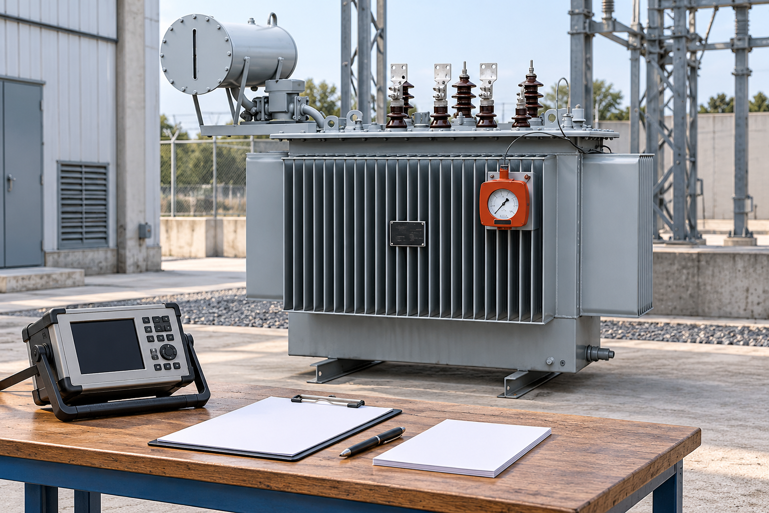
Resistance grounding inserts a specified resistance in the neutral-to-earth path. Its purpose and current objective must be defined by the system study. High-resistance and low-resistance applications differ in their fault-current objectives, protection arrangements and operating policies. Those descriptions are not permission to continue operating any faulted network.
The designer must assess system charging current and the relevant network conditions, particularly where a low earth-fault current is intended. The selected resistance, insulation duty, time rating and monitoring arrangement must work together. A resistor with a calculated ohmic value is not a complete grounding package if fault detection, open-circuit monitoring or operating response has been omitted.
Some applications may permit a controlled response to a first earth fault under defined conditions; others require rapid disconnection. That decision belongs to the approved protection and operating policy, including personnel safety and equipment insulation. Avoid using an article’s continuity discussion as authority to leave a fault in service. Document who receives the alarm and what actions are required.
Reactance grounding uses an intentionally selected reactor. Its fault-current and voltage behavior differs from resistance grounding, so it should not be specified by substituting an inductive device into a resistor calculation. The network model, protective response and abnormal-voltage assessment must support the chosen arrangement.
Resonant grounding uses compensation associated with the system’s earth-fault conditions. Network capacitance and changes in connected circuits matter. The associated tuning, control and protection requirements make it a distinct application. A method name in a bid does not establish that the supplier has evaluated the actual network configurations.
The IEEE neutral grounding devices project page identifies grounding transformers, resistors, reactors and ground-fault neutralizers within the standards topic. Its public scope explains why these are different equipment categories. The project must specify the applicable issued standard and edition; a draft or revision project is not an equipment compliance certificate.
An ungrounded system has no intentional neutral grounding connection in the relevant arrangement, but it still has capacitance and insulation paths to earth. Earth-fault behavior therefore cannot be understood by assuming that no current can flow. The designer must evaluate detection, voltage displacement and abnormal conditions using the actual network.
An earth fault can change the relationship between phase conductors and earth. Connected insulation and voltage-measurement equipment must be assessed for that duty. Detection and location can require dedicated functions and operating procedures. The apparent ability of some loads to keep running does not demonstrate that the installation is safe to operate indefinitely with a fault.
A second earth fault or a different network condition can have substantially different consequences from the first event being considered. The operating policy should state the response to an initial indication, the permitted investigation boundary and the circumstances requiring isolation. Treat continued operation as a controlled system decision, not a default benefit of the method.
| Method | Main design consequence | Questions to settle before approval |
|---|---|---|
| Solid grounding | Fault current follows the full system impedance without an intentional neutral device impedance | Are equipment duty and clearing performance adequate? |
| Resistance grounding | A selected resistance shapes neutral earth-fault current | Are current objective, charging current, time duty and monitoring coordinated? |
| Reactance grounding | A selected reactor influences fault current and voltage behavior | Does the network study support reactor duty and protection? |
| Resonant grounding | Compensation depends on the network earth-fault characteristics | How are configuration changes, tuning and detection handled? |
| No intentional neutral grounding | Capacitance and insulation paths remain relevant | How are voltage displacement, fault detection and operating response controlled? |
| Grounding transformer arrangement | An additional transformer establishes a neutral reference | Are its connection, fault duty and grounding device coordinated? |
This table compares review questions rather than assigning a universal winner. A method can address one operating objective while creating another requirement. Keep the selected grounding arrangement and its protection response together in the design decision.
Parallel sources, bus ties and multiple grounding points can change the network model. Confirm which neutral devices are connected in each operating mode and how their contributions affect fault current. Two sources that are acceptable separately may not have the same grounding behavior when paralleled. The protection study should cover the permitted modes explicitly.
Include standby generators, temporary supplies and future expansions where they are part of the approved design scope. A change in connected cable length can affect capacitance-related assumptions. A change in winding connection or source availability can affect the neutral reference. Establish a change-control trigger so those alterations lead to review rather than silent drift.
The substation protection zones guide and substation grounding system guide address complementary boundaries. Neutral grounding affects fault quantities used by protection; the installation grounding system also addresses the physical earthing and bonding arrangement. Their drawings and calculations must remain consistent.
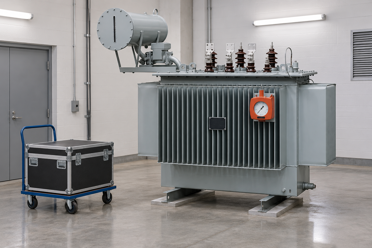
Before energization, match the installed transformer terminals, grounding device and conductor arrangement to the approved drawings. Confirm the equipment ratings and test evidence. Tests for a resistor, reactor or grounding transformer are equipment-specific and must use the manufacturer’s requirements and approved limits. An insulation test should not inadvertently include connected electronics or other unsuitable circuits.
Verify the relevant earth-fault detection, alarm, trip and monitoring paths. Where the design relies on an open-resistor alarm or another supervision function, test the defined condition using the approved facilities. Record the expected response and the actual receiving equipment. A local indication alone does not prove that the operator will receive an actionable alarm.
Use the switchgear site acceptance checklist to connect equipment records with installed protection behavior. Confirm restoration after tests, including temporary blocks and connections. Record the operating modes represented by the tests and any study assumptions that remain to be verified.
An inquiry should identify the system side, voltage and frequency, winding connection, intended grounding method, fault-current objective and protection requirements. For a grounding device, include the required duty, duration, environment, terminals and monitoring. State which information is confirmed and which depends on the final study. This allows the supplier to offer a defined package instead of guessing at the intended network.
Request a single-line diagram, terminal arrangement, equipment data, relevant test records and the final functional description. Clarify responsibility for the network study and the field protection integration. The transformer supplier, grounding-device supplier and switchgear integrator may each own different evidence. Assign those responsibilities before acceptance.
At handover, retain a configuration-specific baseline and a clear response policy for earth-fault alarms. Later changes to sources, cable networks or neutral devices should be checked against that baseline. The most useful grounding choice is one that remains documented and operable as the installation changes, not one selected by a general preference without an application record.
The following educational lecture introduces neutral grounding concepts. It supports understanding of the comparison; project operating decisions and device ratings still require the approved network study and applicable rules.

Further learning: Power Systems-Neutral Grounding — sankethika. Educational background; this is not an operating authorization. Open the video on YouTube.
No. Tank grounding is part of protective equipment bonding, while neutral grounding defines a circuit reference and earth-fault path. Both need an approved arrangement, and one does not replace the other.
No. Availability depends on the winding connection and the supplied terminal arrangement. Confirm the offered design. A grounding transformer may be required in some systems that lack the needed neutral reference.
No. Continued operation, if permitted, depends on the specific system, insulation duty, detection and operating policy. The approved protection study and local requirements determine the response.
Review it when sources, parallel operating modes, cable networks, winding connections, grounding devices or protection arrangements change. Those changes can invalidate the assumptions behind the original selection.






