
 Shenheng Power Equipment Co., Ltd.
- Home
- Products
Products
Since 2001, Shenheng Power has been a trusted manufacturer of power transmission and distribution equipment, delivering reliable electrical solutions globally.

- Solutions
- News & Blog
- Service
- About Us
- Contact Us
Since 2001, Shenheng Power has been a trusted manufacturer of power transmission and distribution equipment, delivering reliable electrical solutions globally.
A transformer bushing power factor test assesses dielectric losses in the bushing’s insulation under a controlled AC test, usually alongside capacitance measurements. Interpretation requires the bushing construction, test connection, voltage, frequency, temperature and previous results. A power factor percentage on its own is not a universal pass or fail decision. The useful outcome is a repeatable condition assessment that distinguishes a genuine insulation change from differences in the measurement setup.
This guide explains what buyers and maintenance engineers should request, how to review the report, and when a change needs specialist investigation. It is not a wiring instruction for a high-voltage test set. Connections, grounding, discharge and restoration must follow the actual bushing manufacturer’s approved procedure.
An insulation system under AC voltage draws a current that includes a capacitive component and a component associated with losses. Power factor expresses real power divided by apparent power. In a simplified measurement, PF = W / (V × I), with consistent units. Laboratories and field instruments may report a percentage instead of a decimal.
For illustration only, 2 W of measured loss and 400 VA of apparent power produce PF = 0.005, or 0.5%. This arithmetic example is not a test voltage recommendation or an acceptance limit. Real measurements require the appropriate instrument method and a correct definition of the insulation being measured.
Dissipation factor, often expressed as tan delta, describes dielectric loss using a related phase relationship. PF and DF are close when losses are small, but they are not identical mathematical quantities. Keep the report’s original quantity and units rather than relabeling one as the other. Ask how temperature corrections and instrument calculations were applied.
The broader transformer insulation resistance test uses a different measurement principle. It does not replace a bushing loss and capacitance assessment, and a favorable result from one method does not automatically resolve a concerning result from the other.
A bushing provides an insulated passage for a conductor through grounded equipment. Its construction determines what can be measured. Some bushings have capacitance-graded insulation and a test or voltage tap; others do not provide that arrangement. Similar external porcelain shapes do not establish identical internal construction.
Record manufacturer, type, serial number, rated data, insulation technology and available tap details. Confirm whether the bushing is installed, stored or disconnected, and identify what other components could influence a test. The asset drawing and bushing manual should establish the relevant terminals and intended grounding arrangement.
Never infer a tap’s permitted test duty from the main terminal voltage rating. A tap may have separate limitations and restoration requirements. If the manual or nameplate information is unavailable, resolve that gap before testing rather than applying a connection diagram copied from another bushing.
The Bureau of Reclamation transformer maintenance reference provides public maintenance background. Its discussion is useful context; the current bushing instructions remain the controlling source for an equipment-specific test plan.
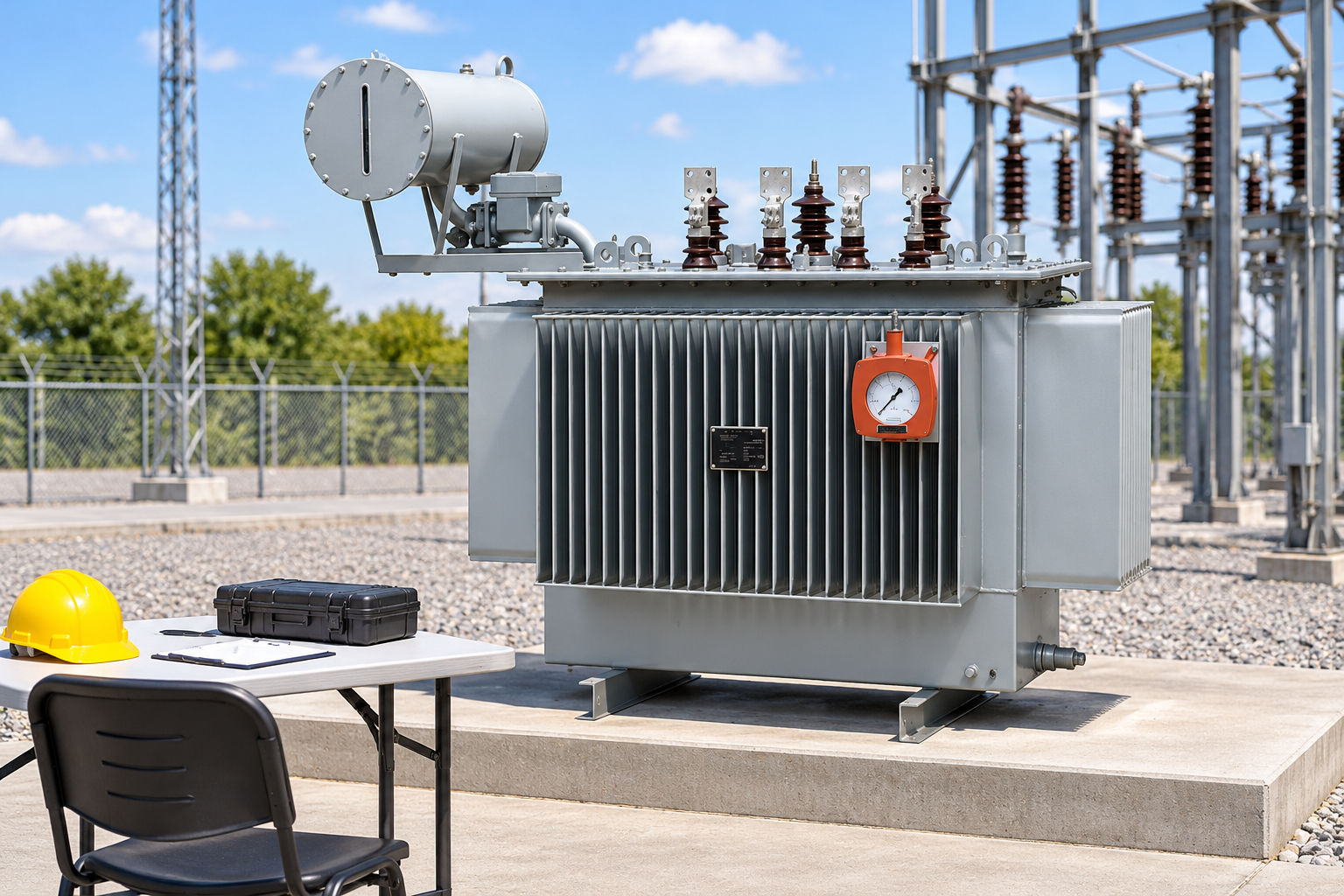
On an applicable capacitance-graded bushing, C1 and C2 describe different insulation sections associated with the conductor, tap and grounded flange. The exact arrangement must be confirmed from the manufacturer’s drawing. A measurement labelled C1 should not be compared with a historical value labelled C2 simply because both are expressed in picofarads.
Reports may also identify grounded, ungrounded or guarded test modes. Those modes establish which current paths are included or excluded. A guard changes the measurement boundary; it does not make a questionable test safe, and it does not eliminate every source of environmental influence.
Ask the testing organization to include the connection reference and measured insulation section in the report. A percentage without that identification may be impossible to reproduce. If an installed bushing test includes additional current paths, describe them explicitly before comparing it with factory results obtained under different conditions.
For bushings without a suitable test tap, a different approved diagnostic approach may be needed. Do not invent C1 or C2 values for a design that does not support them. A specialist should explain what the selected method measures and how its result will be evaluated.
Power factor or dissipation factor and capacitance provide different information. A change in loss behavior can indicate a change in the dielectric system or measurement conditions. A capacitance change can suggest a change in the insulation structure or the measured current paths. Their combination helps define what to investigate.
Compare against the relevant factory or nameplate baseline, previous comparable tests and any manufacturer-specific assessment guidance. Do not substitute a generic internet percentage for the actual acceptance basis. Differences in bushing design, material, temperature and measurement method can make a universal rule misleading.
Look for repeatability. If a result changes sharply when conditions or connections change, document the sequence and investigate the cause. A single favorable retest should not erase the original result without an explanation. Keep both measurements and record why the final assessment relies on one of them.
The following table describes evidence to request. It contains no universal numerical limits and should be adapted to the asset’s approved testing procedure.
| Report item | Why it matters | Question for the testing team | Evidence needed |
|---|---|---|---|
| Bushing identity and construction | Different designs require different methods | Is the test applicable to this exact bushing? | Nameplate, manual and serial number |
| Measured insulation section | C1, C2 and combined paths differ | What was included in the measurement? | Connection reference and test-mode record |
| PF or DF quantity and units | Similar labels can conceal different quantities | Is this a percentage, decimal PF or tan delta? | Original instrument output |
| Capacitance baseline | Structural comparisons require the correct reference | Which factory or historical value was used? | Baseline result and comparable method |
| Temperature and correction | Condition changes can affect comparison | Was a correction justified for this technology? | Measured temperature and correction source |
| Surface and weather conditions | Leakage can influence the result | Were contamination and moisture controlled? | Condition notes and any cleaning record |
| Final restoration | The bushing must return to its intended arrangement | Were tap covers and grounding restored correctly? | Signed restoration check |
A wet or contaminated external surface can create current paths that influence a measurement. Test lead routing, nearby energized apparatus, electrical interference and the grounding arrangement can also matter. Record conditions rather than assuming every rise in loss reflects internal deterioration.
Temperature comparison requires care. Use the correction guidance applicable to the insulation technology and method. Applying a convenient generic correction to every bushing can conceal a real difference or create an artificial one. If correction is uncertain, preserve both the measured result and its temperature and label the limitation.
An unexpectedly negative or unstable reported value is a reason to investigate the measurement, not a claim that the insulation is better than lossless. Check the method, interference, connections and instrument guidance through the qualified team. Do not convert an anomalous result into a pass by changing its sign.
Visual evidence also matters. The oil-type transformer bushing inspection guide helps organize observations of the exterior. Surface condition and leakage should be recorded alongside electrical results, without treating a clean photograph as proof of internal health.
The work plan should identify isolation boundaries, stored-energy controls, instrument capability, the approved connection method and who authorizes restoration. The US electrical work safety requirements are a reference for applicable US work; local law and the site procedure determine the actual requirements elsewhere.
Restoration deserves its own check. Test taps, covers, disconnected conductors and grounding arrangements must return to their documented operating state. An assessment is incomplete if it records only the measurement and leaves the equipment configuration unverified.
If a bushing is replaced, retain the old and new identities, baseline measurements, installation record and any associated oil work. These records make the next condition comparison meaningful. The commissioning reviewer should also consider whether the replacement affects clearances, connections or other equipment interfaces.
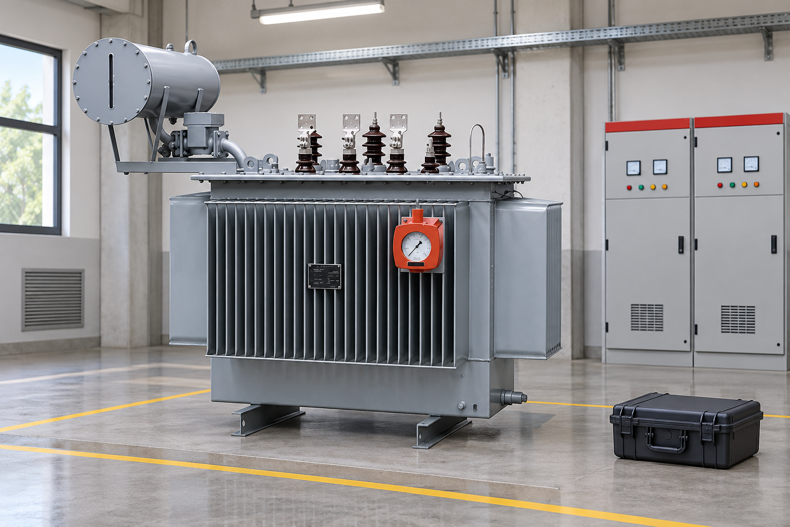
Separate three questions: is the measurement valid, does it differ meaningfully from a comparable baseline, and what does that difference imply for this asset? Each question needs evidence. A specialist may request repeat testing under controlled conditions, other diagnostics or manufacturer review before issuing the operating recommendation.
Related measurements, such as the transformer excitation current test, can contribute to a broader transformer investigation but do not directly certify a bushing. Select them because they address a defined hypothesis, not because a large bundle of tests appears reassuring.
For procurement, request bushing type, manufacturer documentation, relevant routine-test records and the intended maintenance access. The 35 kV oil-immersed transformer provides equipment context for that discussion. Confirm the actual bushing configuration in the offer; do not infer it from the illustration or assume every option has a test tap.
For a newly commissioned asset, agree who owns the baseline and where it will be stored before the testing contractor leaves. A signed report should distinguish measurements taken before installation from those obtained in the final installed configuration. Include any exceptions that prevent direct comparison. When the next maintenance team retrieves the record, it should be able to reproduce the method and understand which conditions changed, without reconstructing the job from photographs or an unexplained spreadsheet percentage.
The educational video below explains transformer components, including the role of bushings. It supports the construction discussion; it does not supply test connections or replace the bushing manufacturer’s instructions.
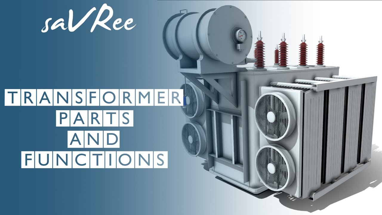
Further learning: Transformer Parts and Functions — saVRee. This educational video supports the topic; it is not a product demonstration or an operating authorization. Open the video on YouTube.
They are related but different quantities. Their numerical values are close at small dielectric losses, but a report should retain the original quantity, calculation method and units rather than treating the labels as interchangeable.
No. The applicable test depends on the actual construction and available tap. Confirm the manufacturer drawing and manual before specifying measurements or comparing results.
No universal percentage applies to every design and condition. Review the appropriate baseline, capacitance, temperature, method, repeatability and manufacturer guidance before making an asset decision.
The test arrangement can differ from the intended operating arrangement. Correct restoration of taps, covers and grounding is essential, and should be verified through the approved equipment-specific procedure before return to service.






